Super Systems X5 User Manual
Page 20
20
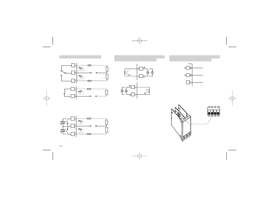
3 - Electrical Connections
3.3.7 OP1-2-3-4 ALARM OUTPUTS
B
Fuse
AL3 load
28
29
OP3
[1]
30
[1]
AL3 load
V
~
Fuse
NC
C
NO
Fuse
AL1 load
31
32
OP1
[1]
33
OP2
[1]
AL2 load
V
~
Fuse
Fuse
AL4 load
34
35
OP4
[1]
V
~
e The relay/triac output OP1/OP2, can be used
as alarm outputs only if they are not used
as control outputs.
3.3.8 OP5 AND OP6 (OPTION)
ANALOG CONTROL OUTPUTS
B
3.3.9 SERIAL COMMUNICATIONS
(OPTION) [2]
B
OP5 and OP6 can be configured for control
action or PV/SP/MV retransmission:
• Galvanic isolation 500Vac/1 min:
• 0/4…20mA, 750
Ω / 15Vdc max.
0/1…5V, 0…10V, 500
Ω / 20mA max..
Notes:
[1] Varistor for inductive load 24Vac only
[2]
A
Please, read the user manual:
“Serial communications and config-
uration software”.
• Galvanic isolation 500Vac/1 min;
Compliance to the EIA RS485 standard
for Modbus/Jbus;
• Termination setting dip switches.
C
SLAVE
13
14
15
20
21
OP6
Cool
load
mA
V,mV
8
9
OP5
Heat
load
mA mV,V
1
2
3
4
SLAVE
X5-SSI-uk 18-03-2009 17:53 Pagina 20