Rt.h1 #rt.h2 – Super Systems X5 User Manual
Page 29
29
4 - Operation
When OP5 and OP6 outputs
are not configured as control
output, they can retransmit the
PV, SP or MV linearized value.
Retransmitted
signal
none
/
P.U.
/
S.P
/
M.U.
Output
range
0=5
/
1=5
/
0=10
0=20
/
4=20
The following parameters define
the low and high range.
Retransmission
low
range
#rt.L1
#rt.L2
#O.rt.I
#O.rt.2
#rt. 1
#rt. 2
RETRANSMISSION
Retransmission
high
range
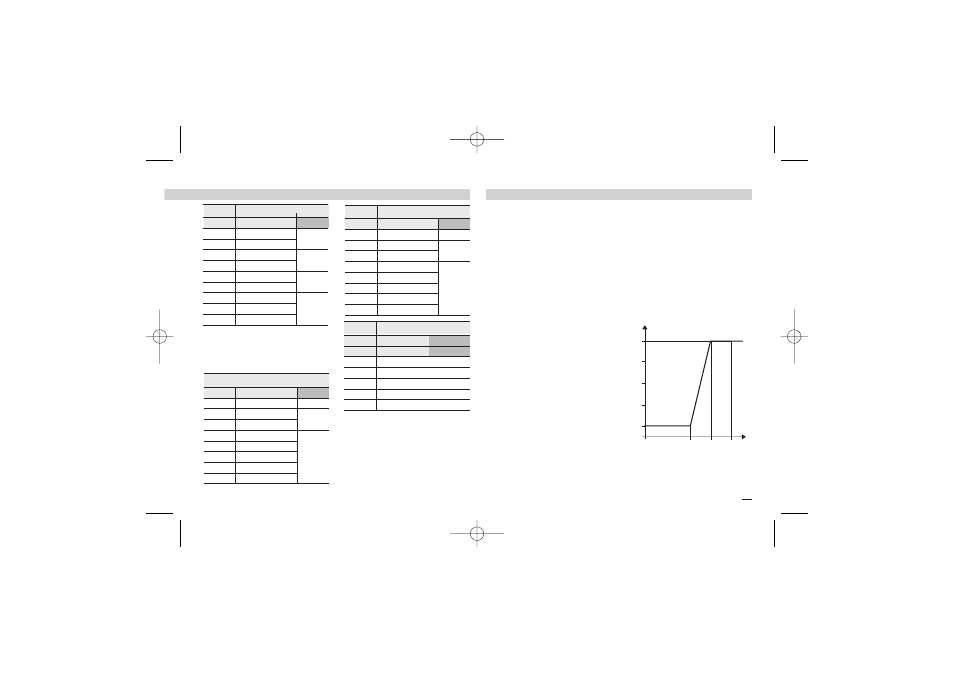
Example:
• T/C S: range 0…1600°C;
• Output range, 4…20 mA;
• Retransmitted signal PV on
800…1200°C range.
#rt.H1
#rt.H2
20
4
800 1200 1600
#retr
= 4=20
#rt.H
= P.U.
#rt.L1
= 800
#rt.H1
=1200
mA
°C
With
rt.lI
greater than
rt.H1
it is possible to obtain
a reverse scale.
Value Description
é
Cn.ty
Tab. 5 Control mode
Of.re
Reverse action
On - Off
Of.di
Direct action
pid.d
Direct action
PID
pid.r
Reverse action
U.dir
Direct action
Modul.
valves
U.reU
Reverse action
H.C.ln
Linear
Heat/
Cool
H.C.Ol
Oil charac.
H.C.H2
Water charac.
Tab. 7 Secondary output (Cool)
Value Description
é
S.C.OP
Off
Not used
OP 2
Relay / Triac
Digital
signal
log
Digital
0=5
0…5 Volt
DC
signal
1=5
1…5 Volt
0=10
0…10 Volt
0=20
0…20 mA
4=20
4…20 mA
Tab. 8 Retransmission outputs
0=5
0…5 Volt
1=5
1…5 Volt
0=10
0…10 Volt
0=20
0…20 mA
4=20
4…20 mA
é
O.rt.1
Tab. 6 Main Output (Heat)
Value Description
é
M.C.OP
Off
Not used
OP 1
Relay / Triac
Digital
signal
log
Digital
0=5
0…5 Volt
DC
signal
1=5
1…5 Volt
0=10
0…10 Volt
0=20
0…20 mA
4=20
4…20 mA
Value Description
é
O.rt.2
X5-SSI-uk 18-03-2009 17:53 Pagina 29