Super Systems 9200 User Manual
Page 27
Model 9200 Programmable Dual-loop Controller
SSi Manual SERIES 9200
27 Programmable Dual-loop
Analog Input Setup
Pressing the Enter key takes you to a two-zone screen with the top zone showing the three inputs.
Pressing the blue up and down keys highlights one of the inputs. Pressing the Enter key takes you to a
menu of parameters that can be assigned to any of the three inputs. Included are thermocouple types,
voltages, and current inputs.
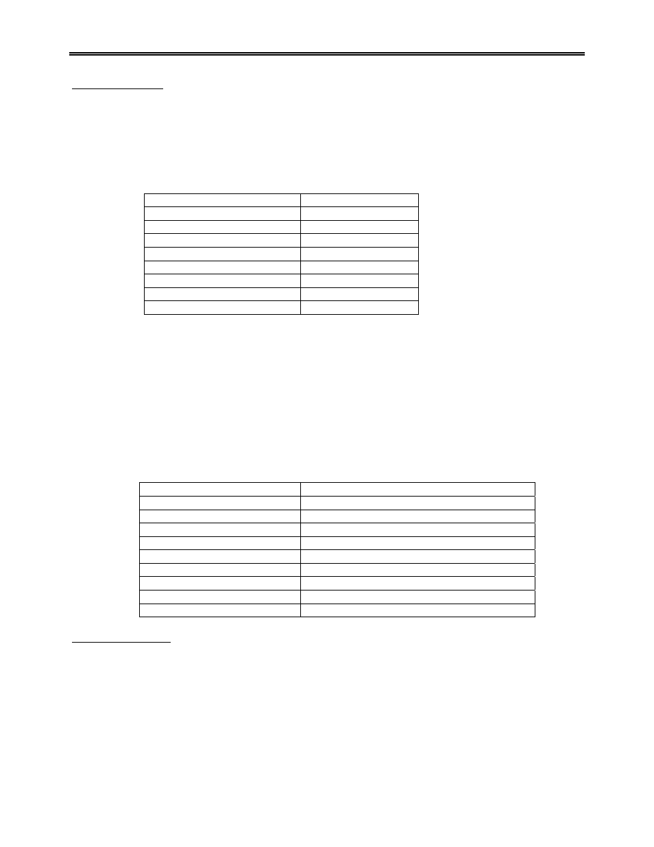
The lower zone of the Input Setup Screen contains a table.
Parameter Value
TC Type
S
Filter Time
0
Initial Scale
0
Full Scale
3000
Decimal Point Location
0
Open TC
Up scale
Input offset
0
Use curve
0
Selecting the input type of Inputs 1 through 3 automatically places that parameter in the first table cell (TC
Type). Using the blue up and down arrow keys to highlight the table cell below the parameter TC Type,
and pressing the Enter key brings up a numeric keypad that allows you to type in the parameter that is
appropriate. If no parameter is necessary simply move the highlight down to the next parameter and enter
that if required. Continue until all values associated/required by the input type have been entered. Pressing
the Esc key takes you back to the Configuration Menu.
NOTE: See the following list of Input Selections
Input type selections for the Series 9200 -
Input Type Options
T/C’s B, C, E, J, K, N, NNM, R, S, T
781.25, 195.3125, 25, 12.5, 2.5 and 1.25 Volts
78.125, 19.53125 Millivolts
4 – 20 mA (124 Ohm precision shunt required)
25 Volts (Requires internal jumper)
12.5 Volts (Requires internal jumper)
781.25 Millivolts (Requires internal jumper)
195.3125 Millivolts (Requires internal jumper)
Analog Output Setup
Pressing the Enter key takes you to a page similar to the input setup with the exception that these are
outputs, not inputs.
Pressing the Enter key when Output 1 is highlighted displays a screen with many parameters listed that
could be assigned to Output 1. Remember that this is NOT control output, but an auxiliary output. For
example you can re-transmit PV1 (Process Variable 1 - %C) to a chart recorder or an analog input board in
a PLC. Pressing the Enter button assigns whichever parameter you have highlighted as the value for the
assignment parameter.