Super Systems 9200 User Manual
Page 32
Model 9200 Programmable Dual-loop Controller
SSi Manual SERIES 9200
32 Programmable Dual-loop
Pressing the Edit button displays a numeric keypad allowing you to change the Span Input 2-range value.
Normally terminals 29(-) and 30(+) have 17.500 mV applied for this step.
After entering the new Span Input value you must press Calibrate. Pressing the Calibrate key stores the
appropriate value. Pressing the Done will return you to the User Calibration Screen.
The current value is displayed directly above the bottom row of buttons as Current Input 2 value: XX.X UV
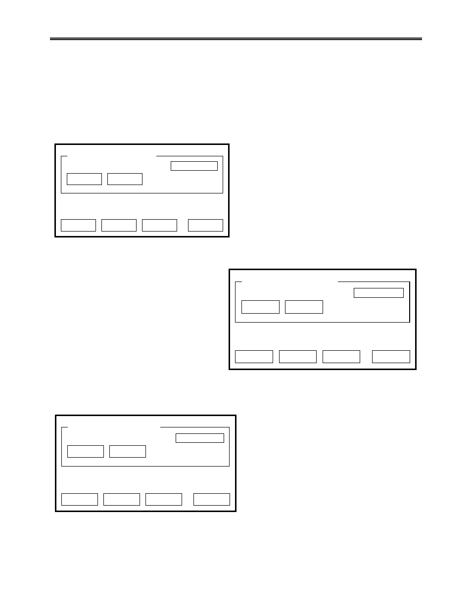
Pressing the Next -> key displays the following calibration screen:
Pressing the Edit button displays a numeric keypad
allowing you to change the Zero Input 3range value.
Normally terminals 27 and 28 are shorted for this
step.
After entering the new Zero Input value you must
press Calibrate. Pressing the Calibrate key stores
the appropriate value. Pressing the Done will return
you to the User Calibration Screen.
The current value is displayed directly above the
bottom row of buttons as Current Input 2 value:
XX.X UV.
Pressing the Next -> key displays the following calibration screen:
Pressing the Edit button displays a numeric
keypad allowing you to change the Span Input
3range value. Normally terminals 27(-) and
28(+) have 65.000 mV applied for this step.
After entering the new Span Input value you
must press Calibrate. Pressing the Calibrate
key stores the appropriate value. Pressing the
Done will return you to the User Calibration
Screen.
The current value is displayed directly above the
bottom row of buttons as Current Input 3 value:
XX.X UV
Pressing the Next -> key displays the following calibration screen:
Pressing the Edit button displays a numeric
keypad allowing you to change the Zero Output 1
value. Measured at terminals 24(-) and 25(+) for
this step. After entering the new Zero Output
value you must press Calibrate. Pressing the
Calibrate key stores the appropriate value.
Pressing the Done will return you to the User
Calibration Screen.
Pressing the Next -> key displays the following
calibration screen:
Pressing the Edit button displays a numeric keypad allowing you to change the Span Output 1 value.
Measured at terminals 24(-) and 25(+) for this step. After entering the new Span Output value you must
Edit
Zero input 3 range 2
Calibrate
<-- Back
Skip
Next -->
DONE
Enter zero voltage (mV)
Edit
Span input 3 range 2
Calibrate
<-- Back
Skip
Next -->
DONE
Enter span voltage (sugg. 65.00 mV)
Edit
Zero Output 1
Calibrate
<-- Back
Skip
Next -->
DONE
Enter span output current (mA)