Input pulsing – Westermo IDW-90 AT User Manual
Page 37
37
6620-3200
4.8 Digital Output
The digital output gives the following functionality:
1. Change over contact (SPDP).
2. Remote controlled.
• Transparent I/O transfer
• Static set ON/OFF
• Pulsed via string pattern “101.. “
3. Follow DCD or DTR.
1. Output Contact
The output shall have the possibility to switch if an incoming call is detected. This will
be detected via an incoming ring signal. It will be controlled via an AT-Command or a
S-register.
2. Remote controlled
The output can be programmed to follow a remote modem data input. A remote unit
can also set/reset the output as well as transferring a sequence of set- and resets of
the output.
3. Follow DCD/Network
The output can be programmable to follow the local DCD or DTR signal.
To accept any operation on the output from remote modems the “Remote IO Enable”
DIP switch must be set “ON”
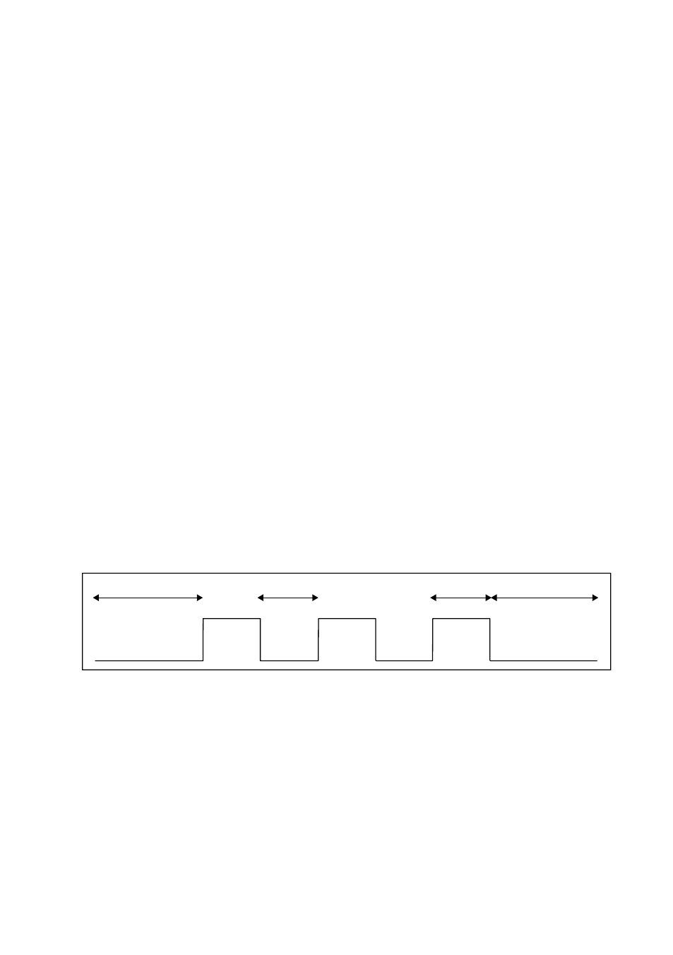
5. Input Pulsing
For the pulsing of an input, some timings must be kept. The parameters t
min
and t
max
are
programmable from 10 to 2550 s. When determining the number of pulses there must be
more than 3t
max
separating the pulse sequences. If a pulse is in active state for more than
3t
max
counting is restarted. When the input has been in its inactive state for more than
3t
max
after,
x
valid pulses, the number of pulses counted is accumulated.
t
L
>3t
max
t
H
>3t
max
tmin < tL < t
max
tmin < tH < t
max