2 camera’s connectors – ARM Electronics MP13DVPDN User Manual
Page 8
Advertising
7
3.2 Camera’s
Connectors
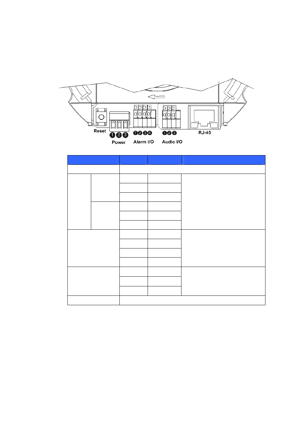
The diagram below shows the vandal proof IP Dome Camera’s reset button and
various connectors. Definition for each connector will be given as follows.
Connector
Pin No.
Definition
Remarks
Reset Button
Restore to factory default
1 Power
2 Reserved
DC 12V
3 GND
1 Power-1
2 Earth
GND
Power
AC 24V
3 Power-2
Power connection
1
Output+
2
Output-
3
Input+
Alarm I/O
4
Input-
Alarm connection
1 Audio
Out
2
GND
Audio I/O
3
MIC IN
Two-way audio transmission
RJ-45
10/100 Ethernet / PoE
Advertising
This manual is related to the following products: