H3C Technologies H3C S9800 Series Switches User Manual
Page 18
10
To support the weight of the chassis, you can prepare a pair of slides rails or rack shelf yourself for the
switch. Make sure the slide rails or rack shelf has the following load-bearing capacities:
•
S9804 switch—A minimum of 40 kg (88.18 lb).
•
S9810 switch—A minimum of 70 kg (154.32 lb).
Installing the installation accessories for the S9804 switch
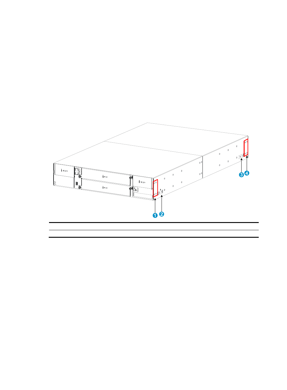
The S9804 switch has one front mounting position (near the network ports) and one rear mounting
position (near the power modules). The switch also has one primary grounding point (with a grounding
sign) and one auxiliary grounding point. Determine the positions for the mounting brackets and
grounding cable before installation.
Figure 14 Installation positions for the mounting brackets and grounding cable
(1) Rear mounting position (power module side)
(2) Primary grounding point
(3) Auxiliary grounding point
(4) Front mounting position (network port side)
Attaching the mounting brackets and chassis rails to the S9804 switch
1.
Align the screw holes in the mounting brackets with the screw holes in the mounting position, as
.
This example uses the rear mounting position.
2.
Use the M4 countersunk screws supplied with the switch to attach the mounting brackets to the
chassis.
3.
Determine the installation positions for the chassis rails based on the rack depth.
4.
Align the screw holes in the chassis rails with the rail mounting holes in the chassis.
5.
Use the M4 screws supplied with the switch to attach the chassis rails to the chassis, as shown
in