S9810 – H3C Technologies H3C S9800 Series Switches User Manual
Page 63
55
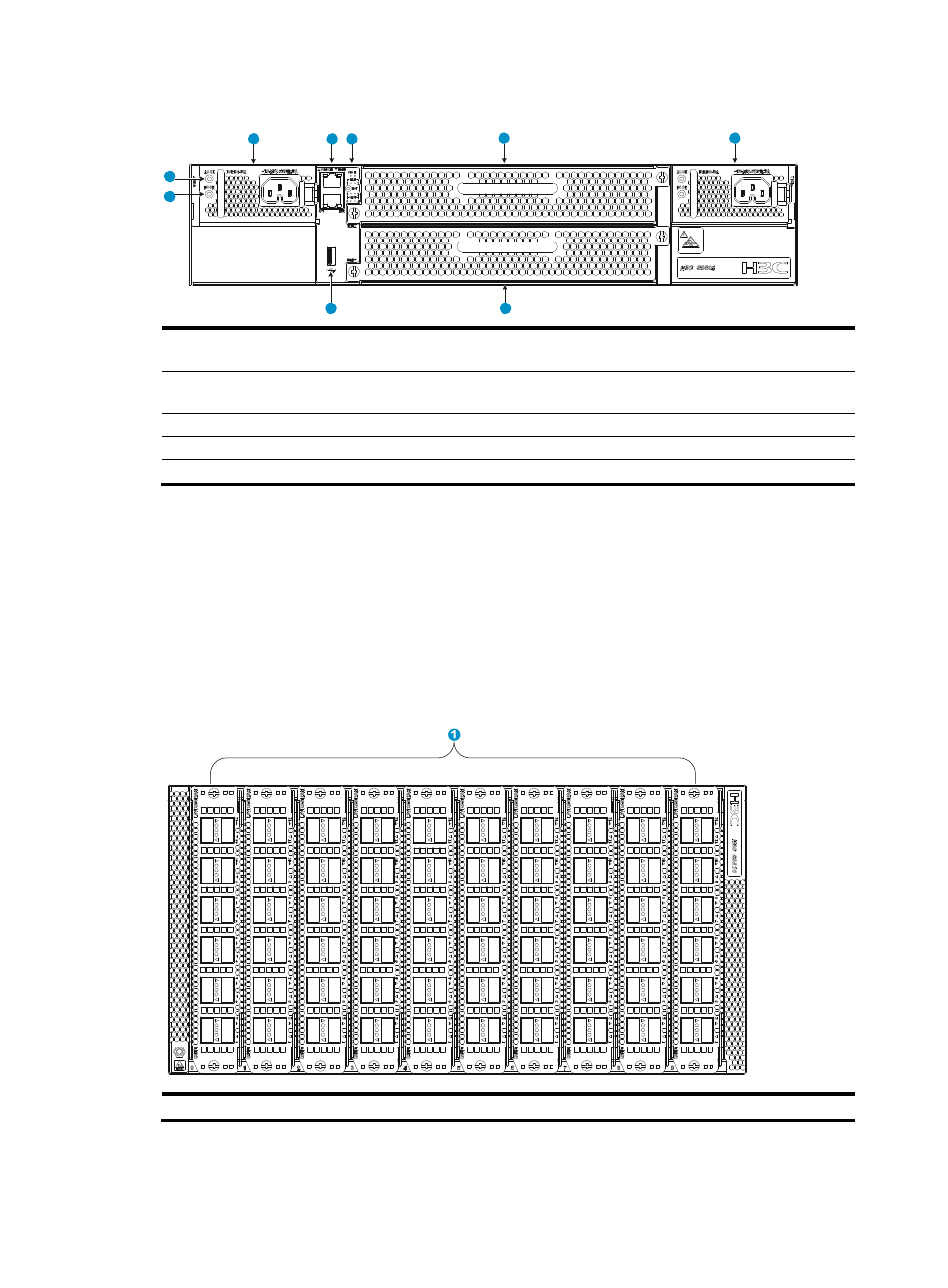
Figure 59 Rear view
(1) Power module slot 1
(2) From top down: console port and
management Ethernet port
(3) From top down: system status LED (SYS), ID LED, fan status LED
(FAN), reset button (RST), and LPU status LED (SLOT)
(4) Fan tray slot 1
(5) Power module slot 2
(6) Fan tray slot 2
(7) USB port
(8) Power output LED (DC OK)
(9) Power input LED (AC OK)
The switch comes with the power module slots empty and the filler panels for the slots as accessories. You
can install one or two power modules for the switch. In the figure, the PSR1800-56A power modules are
installed in the power module slots.
To ensure good heat dissipation, you must install two fan trays of the same model for the switch. In the
figure, the LSVM2S9800FAN fan trays are installed in the fan tray slots.
S9810
Figure 60 Front view
(1) LPU slots 0 to 9
The switch comes with filler panels in all LPU slots except slot 0. In the figure, the LSV1QGS12SA1 LPUs
are installed in the LPU slots.
1
2
3
4
5
6
7
8
9