Other specifications, Cooling system, Cooling system for the s9804 switch – H3C Technologies H3C S9800 Series Switches User Manual
Page 68
60
Other specifications
Table 15 Other specifications
Model
System leakage current
standard
Fusing current
Fireproofing standard
•
S9804
•
S9810
•
EN60950-1
•
GB4943
•
IEC60950-1
•
UL60950-1
15 A
•
EN60950-1
•
GB4943
•
IEC60950-1
•
UL60950-1
Cooling system
The cooling system of the switch includes the air vents in the chassis, fan trays, and built-in fans of power
modules. To guarantee the performance of this cooling system, consider the ventilation design for the
installation site when you choose a fan tray assembly and plan the installation site for the switch.
Cooling system for the S9804 switch
You must install two fan trays of the same model for the S9804 switch: LSVM1S9800FAN and
LSVM2S9800FAN:
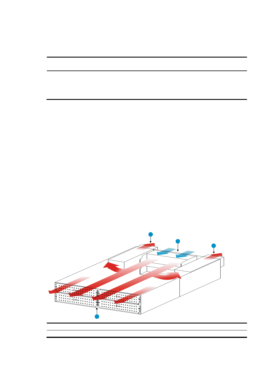
•
When the LSVM1S9800FAN fan trays are used, ambient air flows in through the air vents in the fan
tray panels, circulates through the chassis and the power modules, and exhausts through the air
vents in the power module panels and port-side panel, as shown in
•
When the LSVM2S9800FAN fan trays are used, ambient air flows in through the air vents in the
port-side panel, circulates through the chassis and the power modules, and exhausts through the air
vents in the fan tray panels and the power module panels, as shown in
Figure 62 Airflow through the switch chassis with the LSVM1S9800FAN fan trays
(1) Power module air vents
(2) Fan tray air vents
(3) Port side air vents
1
1
2
3