Configuration example, Network requirements, Configuration procedure – H3C Technologies H3C S7500E Series Switches User Manual
Page 169
15-12
z
After a tunnel interface is deleted, all the above features configured on the tunnel interface will be
deleted.
z
To encapsulate and forward IPv6 packets whose destination address does not belong to the
network segment where the receiving tunnel interface resides, you need to configure a static route
or dynamic routing for forwarding those packets through this tunnel interface. If you configure a
static route to that destination IPv6 address, specify this tunnel interface as the outbound interface,
or the peer tunnel interface as the next hop. A similar configuration needs to be performed at the
other tunnel end. If you configure dynamic routing at both ends, enable the dynamic routing
protocol on both tunnel interfaces. For the detailed configuration, refer to IPv6 Static Routing
Configuration or other routing protocol configurations in the Layer 3 - IP Routing Configuration
Guide.
Configuration Example
Network requirements
As shown in
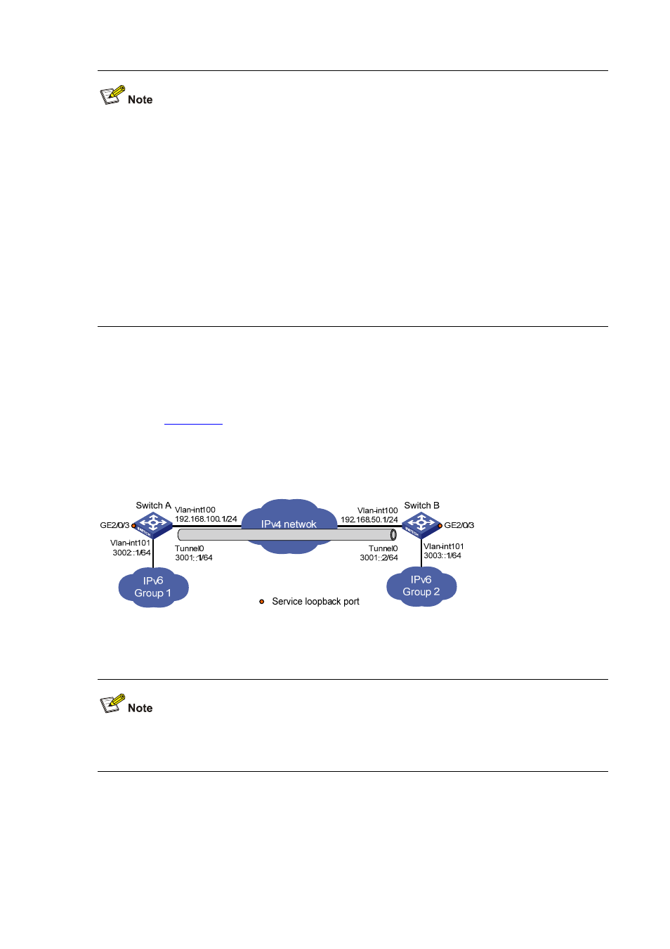
, two IPv6 networks are connected to an IPv4 network through Switch A and
Switch B respectively. Configure an IPv6 manual tunnel between Switch A and Switch B to make the
two IPv6 networks reachable to each other.
Figure 15-8 Network diagram for an IPv6 manual tunnel
Configuration procedure
Make sure that Switch A and Switch B have the corresponding VLAN interfaces created and are
reachable to each other.
z
Configuration on Switch A
# Enable IPv6.
<SwitchA> system-view
[SwitchA] ipv6