6to4 tunnel configuration example, Network requirements, Configuration procedure – H3C Technologies H3C S7500E Series Switches User Manual
Page 174
15-17
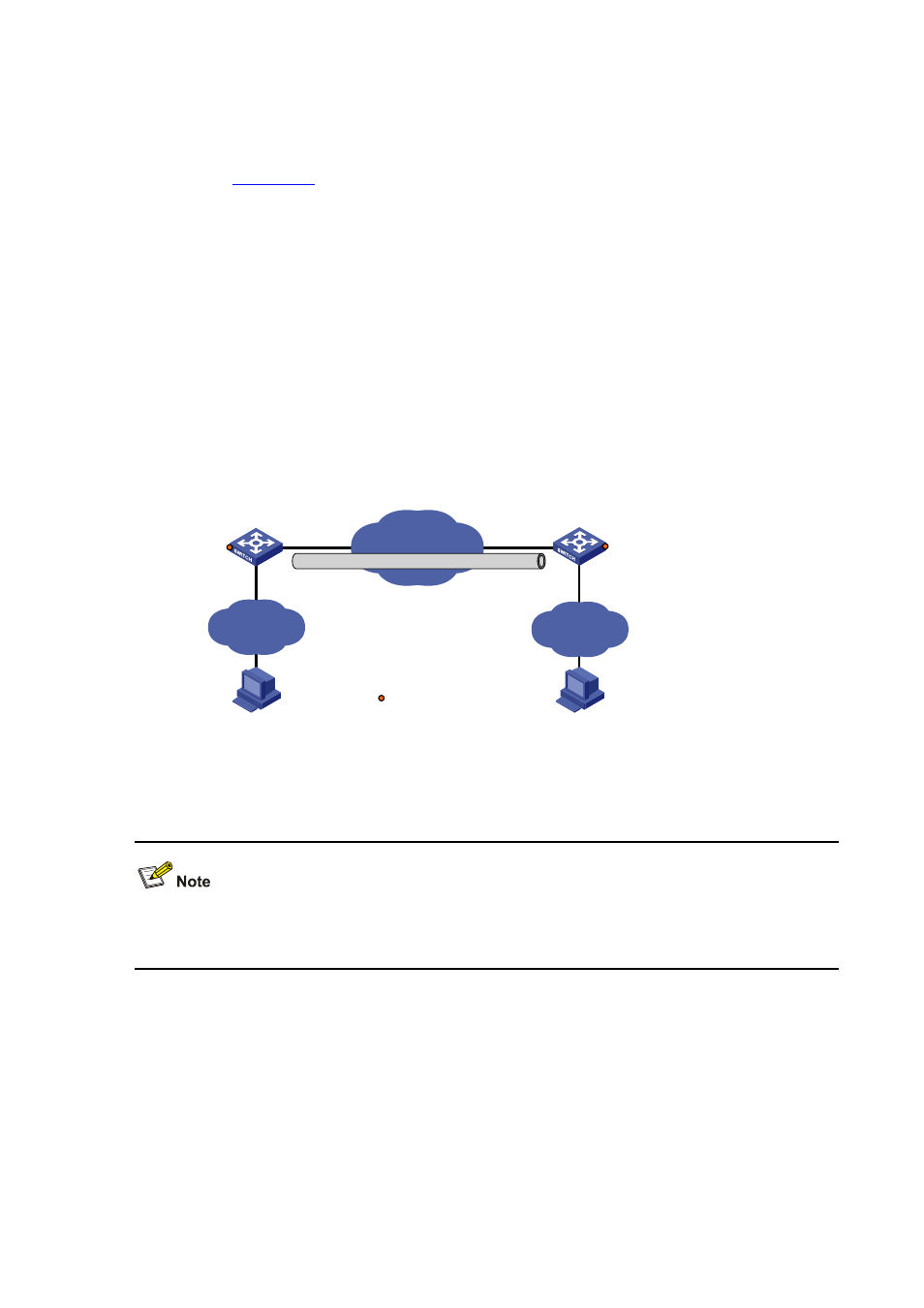
6to4 Tunnel Configuration Example
Network requirements
, two 6to4 networks are connected to an IPv4 network through two 6to4
switches (Switch A and Switch B) respectively. Configure a 6to4 tunnel to make Host A and Host B
reachable to each other.
To enable communication between 6to4 networks, you need to configure 6to4 addresses for 6to4
switches and hosts in the 6to4 networks.
z
The IPv4 address of VLAN-interface 100 on Switch A is 2.1.1.1/24, and the corresponding 6to4
prefix is 2002:0201:0101::/48 after it is translated to an IPv6 address. Assign interface tunnel 0 to
subnet 2002:0201:0101::/64 and VLAN-interface 101 to subnet 2002:0201:0101:1::/64.
z
The IPv4 address of VLAN-interface 100 on Switch B is 5.1.1.1/24, and the corresponding 6to4
prefix is 2002:0501:0101::/48 after it is translated to an IPv6 address. Assign interface tunnel 0 to
subnet 2002:0501:0101::/64 and VLAN-interface 101 to subnet 2002:0501:0101:1::/64.
Figure 15-9 Network diagram for a 6to4 tunnel
Vlan-int100
2.1.1.1/24
Vlan-int100
5.1.1.1/24
Vlan-int101
2002:0201:0101:1::1/64
Vlan-int101
2002:0501:0101:1::1/64
Switch A
6to4 switch
Host A
2002:0201:0101:1::2/64
Host B
2002:0501:0101:1::2/64
6to4
Group 1
IPv4 netwok
Switch B
6to4 switch
6to4
Group 2
Tunnel 0
2002:0201:0101::1/64
Tunnel 0
2002:0501:0101::1/64
Service loopback port
GE2/0/3
GE2/0/3
Configuration procedure
Make sure that Switch A and Switch B have the corresponding VLAN interfaces created and are
reachable to each other.
z
Configuration on Switch A
# Enable IPv6.
<SwitchA> system-view
[SwitchA] ipv6
# Configure an IPv4 address for VLAN-interface 100.
[SwitchA] interface vlan-interface 100
[SwitchA-Vlan-interface100] ip address 2.1.1.1 24
[SwitchA-Vlan-interface100] quit