Configuration procedure – H3C Technologies H3C S7500E Series Switches User Manual
Page 80
7-3
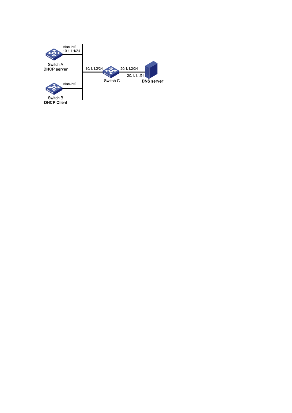
Figure 7-1 Network diagram for DHCP client configuration example
Configuration procedure
1) Configure Switch A
# Specify the IP address of VLAN-interface 2.
<SwitchA> system-view
[SwitchA] interface vlan-interface 2
[SwitchA-Vlan-interface2] ip address 10.1.1.1 24
[SwitchA-Vlan-interface2] quit
# Enable the DHCP service.
[SwitchA] dhcp enable
# Exclude an IP address from automatic allocation.
[SwitchA] dhcp server forbidden-ip 10.1.1.2
# Configure DHCP address pool 0 and specify address range, lease duration, DNS server address,
and a static route to network segment 20.1.1.0/24.
[SwitchA] dhcp server ip-pool 0
[SwitchA-dhcp-pool-0] network 10.1.1.0 mask 255.255.255.0
[SwitchA-dhcp-pool-0] expired day 10
[SwitchA-dhcp-pool-0] dns-list 20.1.1.1
[SwitchA-dhcp-pool-0] option 121 hex 18 14 01 01 0A 01 01 02
2) Configure Switch B
# Enable the DHCP client on VLAN-interface 2.
<SwitchB> system-view
[SwitchB] interface vlan-interface 2
[SwitchB-Vlan-interface2] ip address dhcp-alloc
3) Verification
# Use the display dhcp client command to view the IP address and other network parameters
assigned to Switch B.
[SwitchB-Vlan-interface2] display dhcp client verbose
Vlan-interface2 DHCP client information:
Current machine state: BOUND
Allocated IP: 10.1.1.3 255.255.255.0
Allocated lease: 864000 seconds, T1: 432000 seconds, T2: 756000 seconds
Lease from 2009.02.20 11:06:35 to 2009.03.02 11:06:35
DHCP server: 10.1.1.1
Transaction ID: 0x410090f0
Classless static route: