Pvst configuration example, Network requirements – H3C Technologies H3C WX5500E Series Access Controllers User Manual
Page 109
Advertising
98
Figure 25 MSTIs mapped to different VLANs
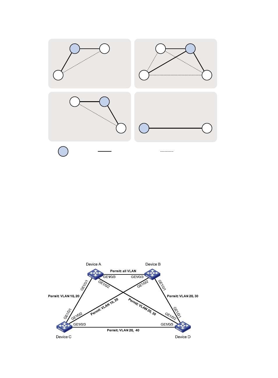
PVST configuration example
Network requirements
As shown in
:
•
Device A and Device B work at the distribution layer. Device C and Device D work at the access
layer.
•
Configure PVST so that packets of VLANs 10, 20, 30, and 40 are forwarded along different
spanning trees.
•
VLANs 10, 20, and 30 are terminated on distribution layer devices, and VLAN 40 is terminated on
access layer devices. The root bridge of VLAN 10 and VLAN 20 is Device A, that of VLAN 30 is
Device B, and that of VLAN 40 is Device C.
Figure 26 Network diagram
A
B
A
B
C
D
C
B
C
MSTI 1 mapped to VLAN 10
A
D
D
Root bridge
Normal link
Blocked link
MSTI 3 mapped to VLAN 30
MSTI 0 mapped to VLAN 20
MSTI 4 mapped to VLAN 40
Advertising