Isolate-user-vlan configuration example, Network requirements, Configuration procedure – H3C Technologies H3C WX5500E Series Access Controllers User Manual
Page 152
141
Isolate-user-VLAN configuration example
Network requirements
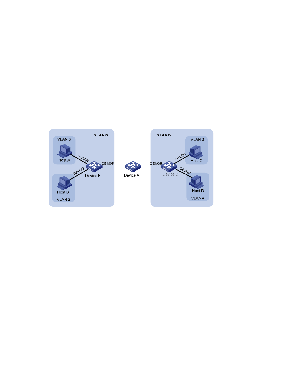
As shown in
, connect Device A to downstream devices Device B and Device C.
Configure VLAN 5 on Device B as an isolate-user-VLAN, assign uplink port GigabitEthernet 1/0/5 to
VLAN 5, and associate VLAN 5 with secondary VLANs VLAN 2 and VLAN 3. Assign GigabitEthernet
1/0/2 to VLAN 2 and GigabitEthernet 1/0/1 to VLAN 3.
Configure VLAN 6 on Device C as an isolate-user-VLAN, assign uplink port GigabitEthernet 1/0/5 to
VLAN 6, and associate VLAN 6 with secondary VLANs VLAN 3 and VLAN 4. Assign GigabitEthernet
1/0/3 to VLAN 3 and GigabitEthernet 1/0/4 to VLAN 4.
As far as Device A is concerned, Device B only has VLAN 5 and Device C only has VLAN 6.
Figure 42 Network diagram
Configuration procedure
The following procedure provides only details about the configuration on Device B and Device C.
1.
Configure Device B:
# Configure the isolate-user-VLAN.
<DeviceB> system-view
[DeviceB] vlan 5
[DeviceB-vlan5] isolate-user-vlan enable
[DeviceB-vlan5] quit
# Create secondary VLANs.
[DeviceB] vlan 2 to 3
# Associate the isolate-user-VLAN with the secondary VLANs.
[DeviceB] isolate-user-vlan 5 secondary 2 to 3
# Configure uplink port GigabitEthernet 1/0/5 to operate in promiscuous mode in VLAN 5.
[DeviceB] interface gigabitethernet 1/0/5
[DeviceB-GigabitEthernet1/0/5] port isolate-user-vlan 5 promiscuous
[DeviceB-GigabitEthernet1/0/5] quit
# Assign downlink ports GigabitEthernet 1/0/1 and GigabitEthernet 1/0/2 to VLAN 3 and
VLAN 2, respectively, and configure the ports to operate in host mode.