Configuration procedure – H3C Technologies H3C WX5500E Series Access Controllers User Manual
Page 60
49
•
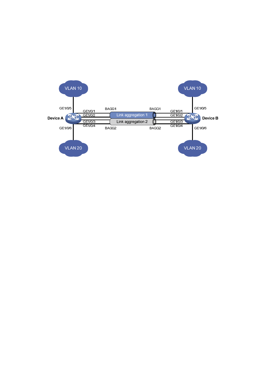
Configure two Layer 2 static aggregation groups (1 and 2) on Device A and Device B, and enable
VLAN 10 at one end of the aggregate link to communicate with VLAN 10 at the other end, and
VLAN 20 at one end to communicate with VLAN 20 at the other end.
•
Configure the load sharing criterion for link aggregation group 1 as the source MAC addresses of
packets and the load sharing criterion for link aggregation group 2 as the destination MAC
addresses of packets to enable traffic to be load-shared across aggregation group member ports.
Figure 12 Network diagram
Configuration procedure
1.
Configure Device A:
# Create VLAN 10, and assign the port GigabitEthernet 1/0/5 to VLAN 10.
<DeviceA> system-view
[DeviceA] vlan 10
[DeviceA-vlan10] port gigabitethernet 1/0/5
[DeviceA-vlan10] quit
# Create VLAN 20, and assign the port GigabitEthernet 1/0/6 to VLAN 20.
<DeviceA> system-view
[DeviceA] vlan 20
[DeviceA-vlan20] port gigabitethernet 1/0/6
[DeviceA-vlan20] quit
# Create Layer 2 aggregate interface Bridge-Aggregation 1, and configure the load sharing
criterion for the link aggregation group as the source MAC addresses of packets.
[DeviceA] interface bridge-aggregation 1
[DeviceA-Bridge-Aggregation1] link-aggregation load-sharing mode source-mac
[DeviceA-Bridge-Aggregation1] quit
# Assign ports GigabitEthernet 1/0/1 and GigabitEthernet 1/0/2 to link aggregation group 1.
[DeviceA] interface gigabitethernet 1/0/1
[DeviceA-GigabitEthernet1/0/1] port link-aggregation group 1
[DeviceA-GigabitEthernet1/0/1] quit
[DeviceA] interface gigabitethernet 1/0/2
[DeviceA-GigabitEthernet1/0/2] port link-aggregation group 1
[DeviceA-GigabitEthernet1/0/2] quit
# Configure Layer 2 aggregate interface Bridge-Aggregation 1 as a trunk port and assign it to
VLAN 10.