Power connections, Signal connections, Voltage input – Precision Digital PD6400 User Manual
Page 19
Model PD6400 High Voltage & Current Meter
Instruction Manual
19
Power Connections
Power connections are made to a two-terminal connector labeled
POWER on Figure 6. The meter will operate regardless of DC polarity
connection. The + and - symbols are only a suggested wiring convention.
Figure 7. Power Connections
Signal Connections
Signal connections are made to a four-terminal connector labeled
SIGNAL on Figure 6. The I+ and I- terminals are used for Channel A
(CH-A) as the current input terminals. The V+ and V- terminals are used
for Channel V (CH-V) as the voltage input terminals.
In addition to the signal connections, the switch labeled TYPE on Figure
6 must be set to AC (alternating current) or DC (direct current) to accept
the corresponding type of voltage and current signals.
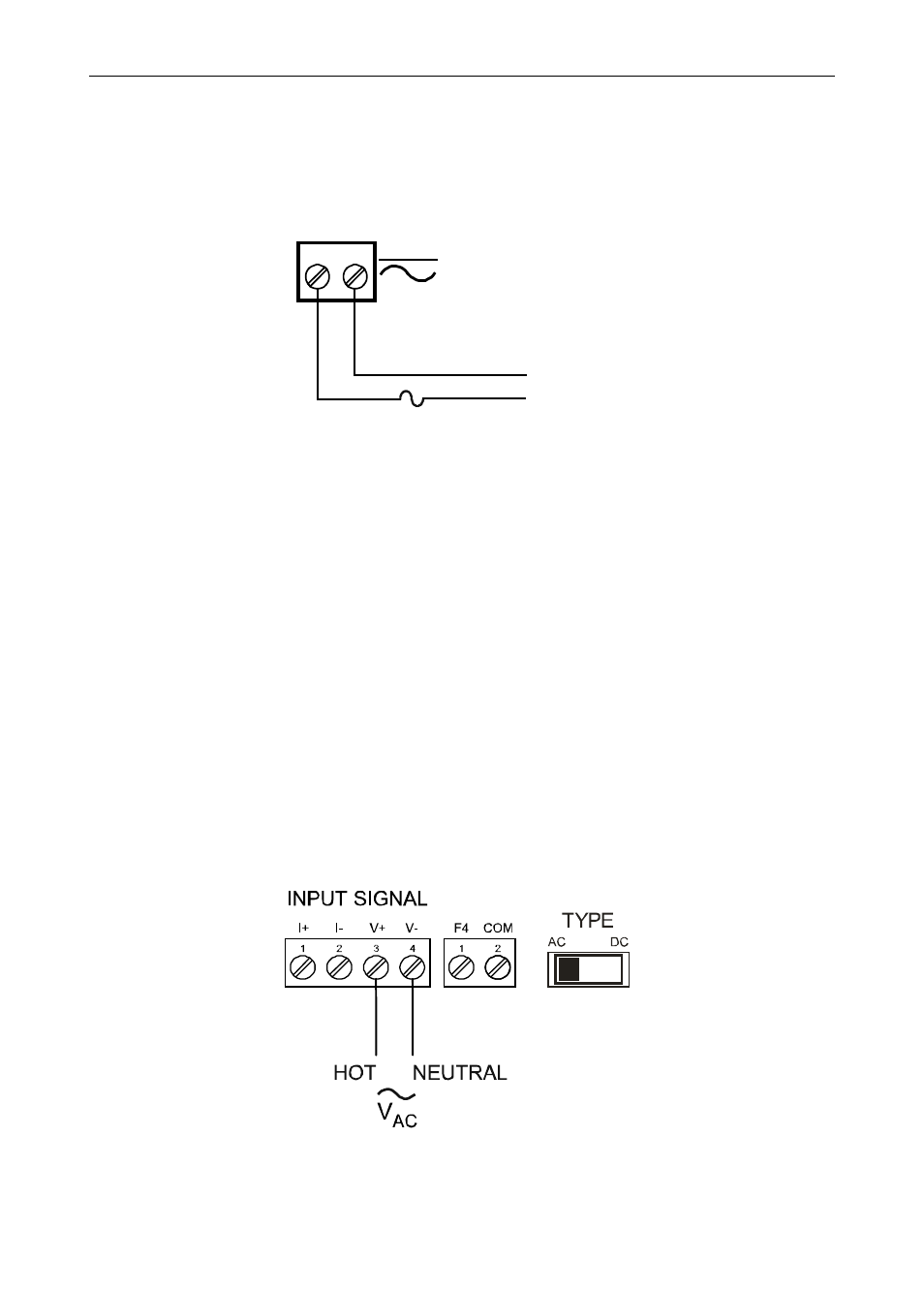
Voltage Input
The following figures show examples of connecting the meter for a
voltage input. Note that in addition to the connections, the AC/DC type
switch much also be set.
Figure 8. AC Voltage Input Connection
AC or DC
POWER
Required External Fuse:
5 A max, 250 V Slow Blow
POWER
+
-