Front panel leds, Latching and non-latching relay operation – Precision Digital PD6400 User Manual
Page 57
Model PD6400 High Voltage & Current Meter
Instruction Manual
57
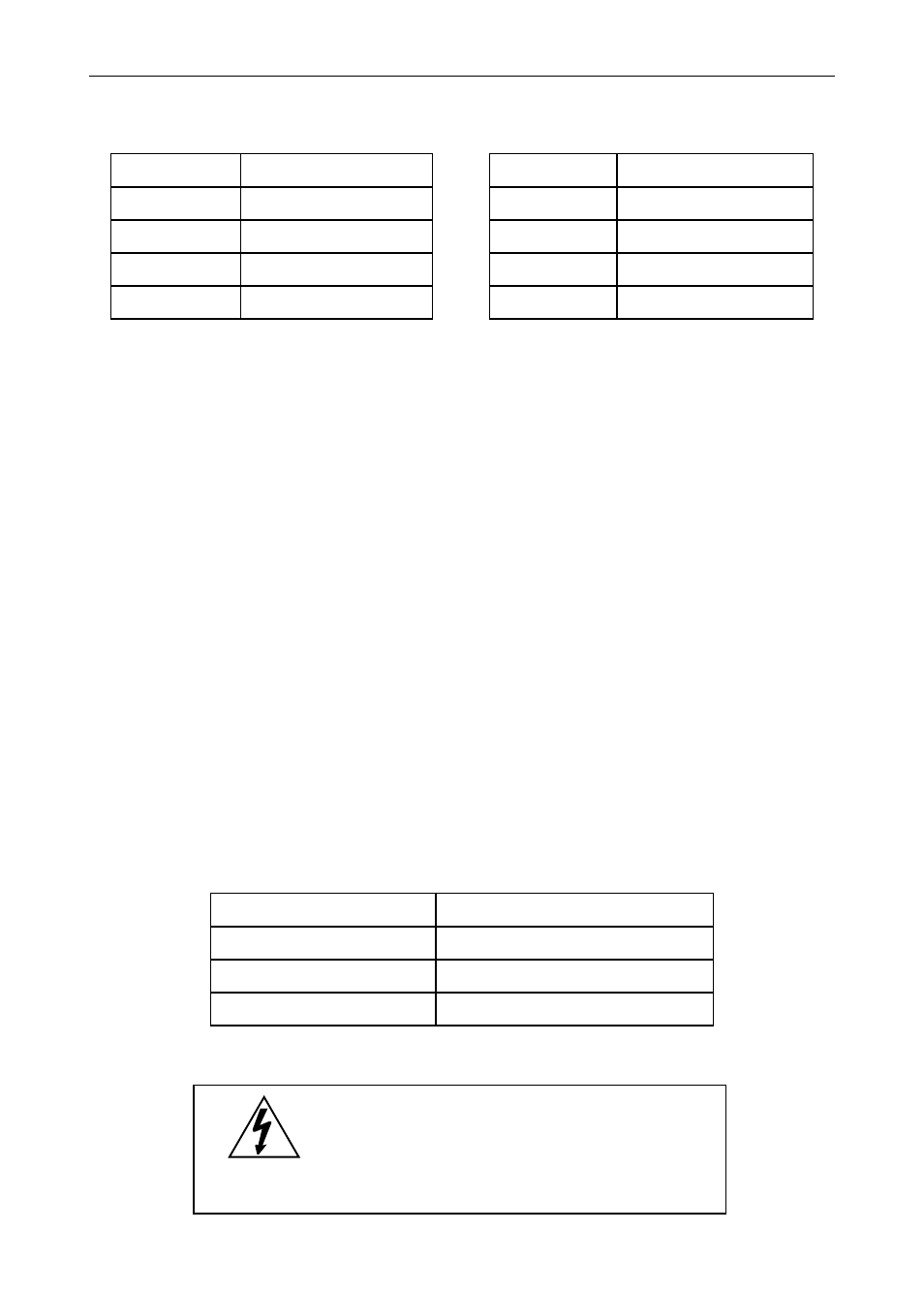
Front Panel LEDs
The LEDs on the front panel provide status indication for the following:
LED
Status
LED
Status
1
Alarm 1
5
Alarm 5
2
Alarm 2
6
Alarm 6
3
Alarm 3
7
Alarm 7
4
Alarm 4
8
Alarm 8
The meter is supplied with four alarm points that include front panel
LEDs to indicate alarm conditions. This standard feature is particularly
useful for alarm applications that require visual-only indication. The
LEDs are controlled by the set and reset points programmed by the
user. When the display reaches a set point for a high or low alarm, the
corresponding alarm LED will turn on. When the display returns to the
reset point the LED will go off. The front panel LEDs responds
differently for latching and non-latching relays.
For non-latching relays, the LED is always off during normal condition
and always on during alarm condition, regardless of the state of the
relay (e.g. Relay acknowledged after alarm condition).
For latching relays, the alarm LEDs reflects the status of the relays,
regardless of the alarm condition. The following tables illustrate how the
alarm LEDs function in relation to the relays and the acknowledge
button (Default: F3 key assigned to ACK):
Latching and Non-Latching Relay Operation
The relays can be set up for latching (manual reset) or non-latching
(automatic reset) operation.
Relay terminology for following tables
Terminology
Relay Condition
On
Alarm (Tripped)
Off
Normal (Reset)
Ack
Acknowledged
The On and Off terminology does not refer to the status of the relay’s
coil, which depends on the fail-safe mode selected.
Warning!
In latching relay mode, latched
relays will reset (unlatch) when
power is cycled.