Remote Processing RPC-210 User Manual
Page 20
SERIAL & SPI PORTS
BASIC
SECTION 4
Page 4-2
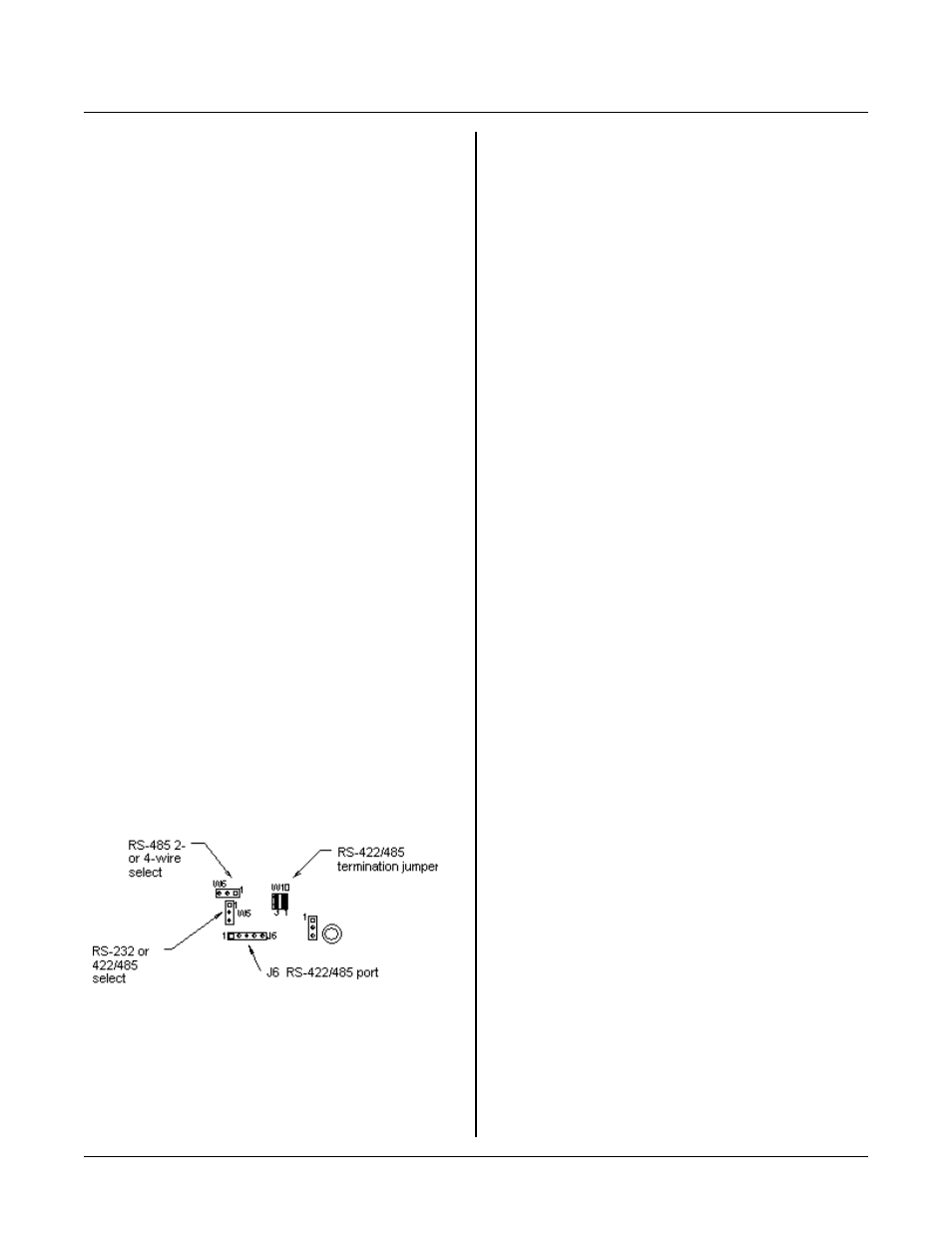
Figure 4-2 CO M 1 jumper locations
Be aware that when continuously printing at this rate,
interr upt proce ssing over head beco mes signific ant.
About 20% of the time is spe nt servicing the interr upt.
This will cause the main program to slow down by that
amoun t.
COM1 SERIAL PORT
COM 1 is either an RS-232 or RS-422/ 485 port. A
VTC -9F serial cable, descr ibed above, is used for RS-
232 level communications. RS-485 is from heade r J6.
NOTE: Some fu nctions of C OM 1 may be used with
interrupt 0 (ITR 0) or the hardware counter
(CTS frequency output). When this is the case,
then COM 1 may not be used.
NOTE:
Make sure J7-3 is jumper ed to J7-5. This
enables C OM 1 interr upts. If this jumper is
removed, the serial port will not work. Also,
CON FIG BAUD must be ex ecuted pr ior to
using COM 1 serial port. This statement
enables inter rupts
Jumper W 5 determines if COM 1 receive is RS-232 or
RS-422/485.
W5[1-2]
RS-232 (de fault)
W5[2-3]
RS-422/485
COM 1 is set to RS-232 at the factory. U se CON FIG
BAUD to set the software to RS-422 or RS-485. When
set to RS-422, the transmitter is always on. R S-485
mode turns on the transmitter only when sending.
CONF IG BAUD also determines the baud rate.
Interrupt 0 is turned off and pointers reset when
RPBASIC-52 is in the immediate mode (pr ogram not
r u n ni ng ) . It is tu r n ed o n o n ly w he n a C O N F I G BA U D
or ON ITR co mma nd is executed and the BASI C is
r u n ni ng . W h at th is m e an s is y ou c an n ot do a P RI N T
#1, nor r ecover any information sent to COM 1 in the
immediate mode.
CTS and RTS
Nomenclature for CTS and RT S, like Txd and Rxd,
changes depending upon which end of the device you are
referencing. For purposes below, RTS is an input to the
RPC -210 and C TS is an outp ut.
CTS and RT S lines are not automatically supported by
RPBASIC-52. T hese lines can be read and controlled as
shown in sample pr ogram s.
WRCT S1.BAS toggles the CTS output line to the device.
The CTS line is used to control sending by an external
device. A high usually enables sending while a low
(negative voltage) holds off a device. The RP C-210
buffers up to 256 characters. If you have received a
message and know it will take time to process the data,
you may want to hold o ff the sender until the data is
processed.
RDRT S1.BAS r eads the current status of the RTS input
line. This line is read to determine if the current device
wants the RPC-210 to start or stop sending data. M any
devices buffer a certain amount of data. If the
transm ission rate is fa ster than the device can h andle it
(as in a printer or cell modem), the RPC-210 m ay be
requested to stop sending for a while. Keep in mind that
while you may stop using the PRINT #1 com mand, the
transmitter on the RPC -210 may still send data until the
buffer is e mpty. If this is a proble m, send out data in
smaller chunks and check the RTS input frequently.
RPBASIC-52 Programm ing Manual difference
CON FIG BAU D 1, 0 does not output 57,600. W hen a
baud code 0 is entered, the rate will be 38,400.
Be aware that when contentiously printing at this rate,
interr upt proce ssing over head beco mes signific ant.
About 25% of the time is spe nt servicing the interr upt.
This will cause the main program to slow down by that
amoun t.
NOTE: When contentiously printing (minutes at a time)
at 38, 400, tick timer s slow dow n. T his is
b e ca u se th e in te r r up t o v er h e ad p r oc e ss in g ti m e
is so great, some 10 mSec tick interrupts are
missed. Ove r a period of 5 minutes, 1 second
o f ti c k t im e a cc u r ac y is lo s t. T h e r ea l t im e
clock is not affected. Tick timer accuracy is not
affected when operating at 19,200 or slower
baud.