Remote Processing RPC-210 User Manual
Page 60
Advertising
TECHNICAL SPECIFICATIONS
SECTION 16
Page 16-3
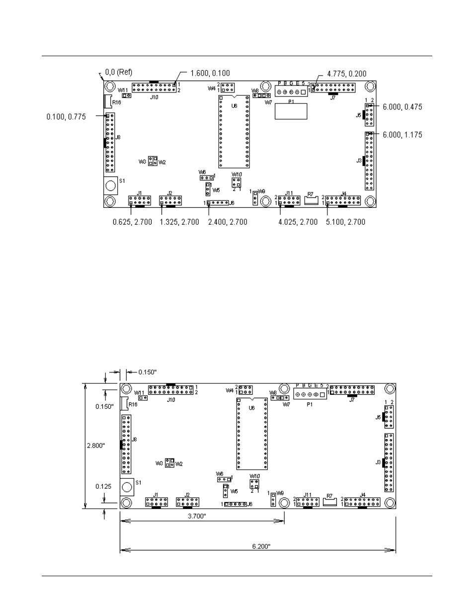
Figure 16-1
Figure 16-2 M ounting hole locations
CONNECTOR POSITION
Connectors shown above ar e on 0.1" spacing.
Dimensions ar e in inches.
BOARD DIMENSION
Below ar e board dimension s and mou nting hole
locations.
Mounting hole diam eters are 0. 175" in 0. 250" pad. Use
0.250" spacers.
Note that the “top” row of holes are 0. 150" from the
edge while the “bottom” row are 0. 125" from the edge.
Advertising