Remote Processing RPC-210 User Manual
Page 46
ANALOG I/O
BASIC
SECTION 10
Page 10-4
K = 200 / 4095
K = .0488
The result is in PSI w hen used as follows:
1000 B = .0488*AIN(0)
The constant can be stored in RAM or Flash memor y.
This “ constant” can be chan ged to com pensate for gain
differences between sensors and the A/D ’s on different
boards. See AIN -3.BA S for a sam ple progr am. . T his
program uses the operating range of a hypothetical
transduc er to com pute an offset a nd constant.
TIMED A/D CONVERSIONS
The O NTI CK or ON IT R constr ucts may b e used to
make periodic conversions. ONTIC K is used for
relatively frequen t conversions (
.
10 times/ second) w hile
ONITR uses the real time clock to initiate a conversion
at a prede term ined date/ time or longer inte rval.
Frequently, A/ D conversions are a part of some other
timed process that che cks general system status.
See AIN-2. BAS for a program that performs conversions
on a timed interval using ONTICK.
MEASURING HIGHER VOLTAGES
Voltages higher than + 2.5V or 5V are measur ed by
inserting a series resistor to the input. A resistor can be
connected directly to the STB-20.
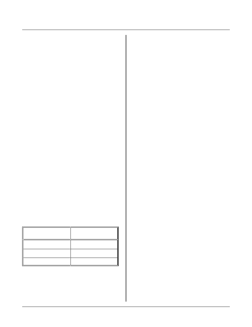
The table below shows resistor values for typical input
voltages using the 0-2.5V range.
Maximum Input
Voltage
Series resistor
3.00
200K
6.25
1.5M
12.25
3.90M
Use the following formula to determine the series
resistance necessar y for a m aximum voltage input:
Rs = Vi * 200,000 - 1, 000,000
0 - 5V range
Rs = Vi * 400,000 - 1, 000,000
0 - 2.5V r ange
Rs is the re sistor value in ohms in ser ies with the inpu t.
Vi is the maximum input voltage. W hen the result of
your ca lculation is negative or zer o, a series r esistor is
not necessary.
Adding a series resistor increases the source impedance
beyond recomm ended values. A wa y to compensate for
this is to put a capac itor at the line at J1 . T his
effectively makes an RC filter. A 0.001 m fd or greater
capacitor is adequate.
NOTE: When an input voltage exceeds the input range,
other channel values are affected.
Due to the high resistan ces involved, you may want to
use a voltage d ivider instea d. If y ou do, don' t forget to
include the 1M ohm resistor to ground (R11) in your
calculations.
Measuring 4-20 mA Current Loops
Curr ent loops are a convenient way to transmit a value
and still assure the integrity of the signal. If the line
should break, a 0 volts (or nearly so) is returned.
A 4-20 ma curr ent loop is converted to 1 - 5V by placing
a 250 ohm resistor across the input of the chan nel to
ground. Since the mea surement range is 1 to 5V, the
count range is reduced by 20% to 3276
CALIBRATION
Ther e are tw o refer ences on the R PC- 210. 5V is
adjustable w hile 2. 5 is not.
You should calibrate 5.00V reference when you need
accuracies greater than 5 counts (7.3 mV @ 5V range)
on any one channel. Using this reference r eturns A-D
readings that are accurate to ±4 counts on any one
channel and up to ±7 counts difference between any two.
5.000V Reference
R16 is used to adjust the maximum, or reference
voltage. Its location is shown in Figure 11-1. When
W11 is installed, A/D and D/A ranges are 0 - 5V. If
W11 is installed, W12 must be set to [1-2].
Norm ally, the r eference is 5. 000 volts. Y ou can adjust
R16 so the reference voltage is between about 4.75 and
5.25 vo lts.
This reference obtains its power from the RS-232 chip.
If the serial ports are heavily loaded, the reference may
not be adjustable to the desired voltage. In this situation,