Remote Processing RPC-210 User Manual
Page 52
EXPANSION PORT & POWER
BASIC
SECTION 12
Page 12-1
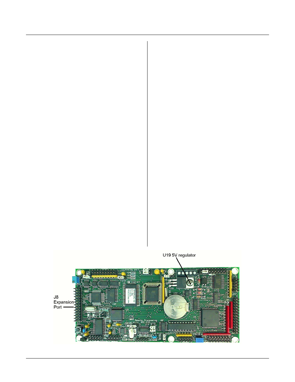
Figure 12-1 Power input and Expansion Port
INTRODUCTION
EXPANSION PORT & POWER
SECT ION 12
E x pa n si on p or t at J8 a ll ow s yo u to c on n ec t o th e r I / O
type cards for expanded capability. Power connector P1
is for ground, + 5, and h igher voltage inputs.
EXPANSION PORT
Keep the connector length between J8 and expansion
card connectors as short as possible (4 inches or less).
Power and ground are available at this connector. Since
the ribbon cable is small gauge and has high resistance,
keep power curr ents as low as possible (less than 100
ma) to prevent ground loop problems. Ground loop
problems m anifest themselves as ran dom rese ts, lockups,
and inaccurate A /D r eadings.
J8 expansion port pin out is sh own at the e nd of this
chapter.
EXTERNAL POWER
The RPC-210 uses + 5V as its primary power. It can
accept + 6V to + 16V at P1 terminals ‘E’ and ‘B’. U19
regulates the voltage down to + 5V.
There are two places to connect + 6 to 16V power,
depending upon operating mode. Two modes are:
Power dow n and non-power down.
Non-Power down voltage is applied to the 'E' terminal
on P1. Jum per W8 to connect regulator output to the
rest of the card. Remove jumper W7. The ‘E’ terminal
line also goes to J8-4.
When o perating th e board in power down m ode, apply
+ 6 to 16 volts to the terminal marked ‘B’. Jumper W7
and W8.
Board + 5 and gro und are available fr om or applied to
appropriate pins at J1, J2, J3, J7, J8, J11, or P1.
The m aximum externa l voltage of 16 vo lts is due to
voltage limitations of the power down circuits and/or
power dissipation of the voltage regulator. The voltage
may be stepped down from higher voltages yet by
putting a regulator (such as a 7812) to P1 pins ‘E’ or
‘B’.
Depending upon the external voltage, you may need a
heat sink on the extra regulator.
Heat Sink
A heat sink under U19 is normally not necessary.
Conditions when you need a heat sink depend upon the
amount of power you expect U19 to dissipate and
ambient temperature.
First ste p is to determ ine the pow er you e xpect U1 9 to
dissipate. T his is calculated as follows:
P(MA X) = (V
BATT
- 5) * I
Where: V
BATT
is battery or supply voltage
I = current into the board.
Current into the board is about 120 mA with no external
cables connected (including serial). Other devices
connected to the bus, I/O p orts, and LC D display w ill
increase + 5V power requirem ents.