Remote Processing RPC-210 User Manual
Page 22
SERIAL & SPI PORTS
BASIC
SECTION 4
Page 4-4
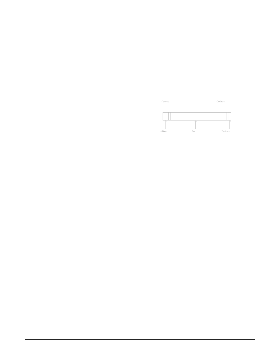
Figure 4-4 Data packet
RS-422/485 Termination network
W 1 0 en a bl e s t he n et w or k te r m in a to r . W h en th e RP C -
210 is the last physic al unit on a netw ork (RS -485) or is
the only unit (RS-422), the receiver must be terminated
to preven t ringing and noise pick up. Insert jum pers into
W10[1-2][3-4]. See Figure 4-2 above for jumper
example.
Only one slave device on a RS-485 network should have
a terminator installed. The host transmitter shou ld also
have a 120 ohm resistor in series with a 0.01 m fd
capacitor . T he term inator on the RPC -210 includes p ull
up and pull down resistors to prevent lines form floating
and generating er roneous char acters.
RS-485 transmitter turn-off
T h e RS - 48 5 tr a n sm i tt e r i s c o nt r ol le d by th e RP B A SI C -
52 operating system. The 485 transmitter is turned off
when the last character is sent. You must specify RS-
485 mode in the CON FIG BAU D 1 comm and.
There is a small potential for having two transmitters on
a t t he s am e ti m e. T h e R S- 4 85 tr a n sm i tt e r o n th e RP C -
210 stays on for approximately ½ character time after
the last byte is sent. Nor mally, this is not a problem
when ba ud rates a re 9600 and above a s receive rs usually
do not respond with 1 mSec anyway. However, if you
are tr ansmitting at 4 800 baud an d below, there is this
potential. When a host (or other peer) is responding,
ensure there is a character time delay before r esponding.
Multidrop Network
You can use the RPC-210 in a m ultidrop network by
u s in g C OM 1 ' s R S -4 2 2/ 4 8 5 p o r t o r e ve n a r a d io m o de m .
Y o u c a n c o nn e ct up to 3 2 u n it s ( in c lu d in g ot he r R P C -
210' s) over a 4 ,00 0 foot ran ge. The num ber of r adio
modems is virtually unlimited.
A network includes a host and one or more devices. The
host transmits data packets to all of the devices, or
nodes, in the network. A data packet includes an
address, com mand, data, and a checksum. See figure 4-
2. The packe t is received by all devices, and ignored by
all except the one addressed.
The relationship described below between nodes and the
host is a maste r-slave. The host dir ects all
c o mm u ni ca ti on . N o de s " d o n o t s pe a k u n le ss sp o ke n to " .
Peer to peer com munication, while possible with the
RPC-210, is not discussed here.
Ther e are m any com municatio n protoco ls. F or this
example, a protocol might look som ething like this:
> 22M B1
The pr otocol starts w ith the < cr> charac ter. This
character synchronizes all units and alerts them that the
next few characters coming down are address and data.
In this case, "> 22" is the units address. "M " is the
comm and and " B1" is the ch ecksum . T he comm and is
terminated with a < cr> character.
The response depends upon the nature of the command.
S u pp o se th e co m m an d M me a ns " r et ur n a d ig it al I/ O
port status". T he RPC-210 could rea d the port and
respond with AA2< cr> . The first A is an
acknowledge, that is no error s were detected in the
message. The data, A2, can be broken do wn as follows:
Bit/line
7 6 5 4 3 2 1 0
Status
1 0 1 0 0 0 1 0 = A2
Lines 1, 5 and 7 are high while the others are low.
The following program fragment uses ON C OM$ and
STR in a network environment. ON C OM$ generates an
interrupt when a < CR> is received. The interr upt
progr am uses a STR fun ction to deter mine if the da ta
packet was addressed to this card.
10 STRING 200,20
20 ON COM$ 1,0,13,1000
30 $(1) = ">05"
.
.
.
1000 $(0) = COM$(1)
1010 A = STR(8,$(0),$(1))
1020 IF A = 0 THEN RETURN
.
.