Remote Processing RPC-210 User Manual
Page 39
COUNTER/TIMERS
BASIC
SECTION 8
Page 8-2
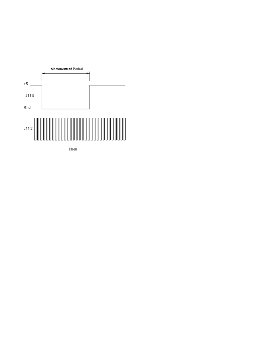
Figure 8-2 Pulse W idth Measurement
USING INTERRUPT 0
Interrupt 0 (INT 0) may be used for COM 1 serial
communications. You cannot simultaneously use INT 0
for the counter and COM 1.
Interrupt 0 is level sensitive. This means that as long as
the line at INT 0 (available at J7-3 or J8-6) is low, code
starting at the line set in ONITR will execute if an RETI
instruction was given. If a RETURN is given, then
interrupts are turned off.
Norm ally this is not going to be a problem using the
counter if your counting rate is greater than 100 Hz. If
the count rate is very slow, then you can monitor the
interrupt line through one of the lines at J3 and use the
ON LIN E multi-tasking command to generate an
interr upt.
If you are using the counter in quadrature mode, then the
only requirement is to reset the interrupt latch:
LINEB,0A700h,0
resets the latch. See COU NT1. BAS for a program
example.
Review EXT ERNA L INTE RRUP TS SECT ION 10 for
more inform ation.
PULSE WIDTH & FREQUENCY
MEASUREMENT
You can measur e a pulse wid th or a fr equency, with
limitations.
Pulse width measurement
COM 1 UART can be put into a mode where the CTS
line outputs a cr ystal contro lled frequ ency. This
frequency is program mable from 9600 H z to 3.6864
MHZ . U sing this output in conjunction with the input
pulse allows p eriod m easure ment.
See COU NT4. BAS program for a list of frequencies and
a demonstra tion program of how to measu re a pulse
width. Note that is program best measures pulse widths
with long dwell periods. Pulse widths may be very short
(> 1 micro-sec ond) but the repetition rate should be less
than 100 Hz.
Pulse width to measure is applied to J11-5. Period
measurem ent begins when the signal is low. If you w ant
to measure a high going pulse, you must put an inverter
in front of the signal.
A reference clock signal is applied to J11-2.
CLOCK4.BAS uses a clock available from COM 1
UART. If the UART is needed, then an external clock
m u s t b e su p pl ie d . A si m pl e 1 M H Z o r 10 M H Z
oscillator applied to J22-2 will work.
A problem m easuring pulse widths using this demo is the
repetition r ate is limited. The pulse w idth (low signa l)
may be under 1 m icro-second. H owever, the repetition
rate shou ld be slower than 100 H z to ensur e reliable
operation. This is because the program has to read and
reset the counter then perform w hat ever analysis on the
incoming data.
Frequency measurement
Frequencies to 20 MH Z may be m easured. T he
program uses the 2 Hz clock output to gate the
frequency. Effectively, gate time is 0. 25 seconds.
Usually this is adequate for high frequency
measurem ents. Note that the gate time is dependent
upon the RTC accur acy. F or very high accuracy you
will need to add an external clock.
A gating signa l is applied to J11-5 w hile the freq uency to
be mea sured is ap plied to J11-2. When the gate signal is
low, the counter is enabled and counts pulses ap plied to
J11-2.