Remote Processing RPC-210 User Manual
Page 9
SETUP AND OPERATION
SECTION 2
Page 2-3
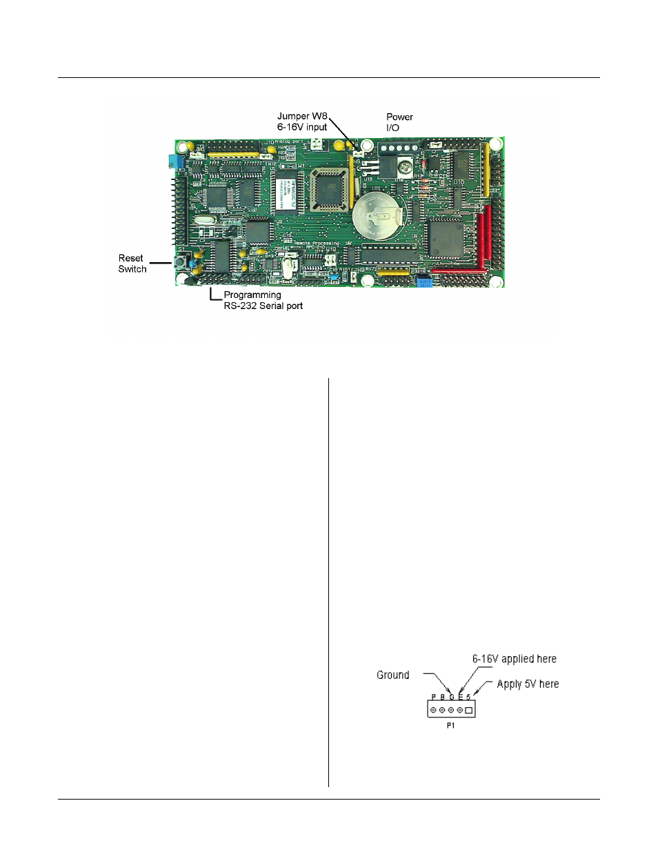
Figure 2-1 Pow er and Serial Progr amming
Figure 2-2 Pow er input locations
FIRST TIME OPERATION
Become familiar with the locations of connectors before
getting started. See Figure 2-1. RPC-210 jumpe rs have
been set at the fa ctory to op erate the system im mediately
using a 6 - 16 V supply. If you have a 5V supply, then
remove jumper W8 and connect the + 5V to P1 terminal
marked ‘5' . F or first time operation, do not install any
connectors or parts unless specified below. Jumpers
should be kept in default positions.
1.
Connect power.
A development system includes a power supply and
cable assembly. Refer to the next two paragraphs
for conn ection instru ctions then m ove on to
paragraph 2.
Develop ment sy stem po wer sup ply
Refer to Figure 2-1 on the next page. Connect the
red w ire on the p ower cable assem bly (P/ N 1725) to
the terminal marked “E” on P1. Black goes to P1
t er m i na l m a r ke d " G" .
You may plug the power supply into a 120 VAC
wall outlet or power strip. P ower may be applied or
removed from the RPC-210 board by plugging the
3.5m m connector from the power supply to the
power cable assembly.
Your ow n powe r supply
The RPC -210 needs + 5 volts or 6 to 16 volts at 300
ma. T he RPC-210 has its own regulator which
supplies 5V to the rest of the card w hen powe r is
applied to the ' E' termin al.
Be careful when using "switching" power supp lies.
Some supplies do not regulate properly unless they
are adequately loaded.
Make sure pow er is off. Conne ct the powe r supply
to one of the appropriately marked terminals on the
RPC-210 as shown below.
Power connector P 1 is designated as ' 5' for 5 volts,
' E' for the external 6-16 volt input, and ' G' for
ground. Other terminals marked ‘B’ and ‘P’ are
discussed in Section 7, REAL TIM E CLO CK.
Connect power to P1 as appropriate from your
supply as shown below.