Remote Processing RPC-210 User Manual
Page 30
DIGITAL LINES
BASIC
SECTION 6
Page 6-2
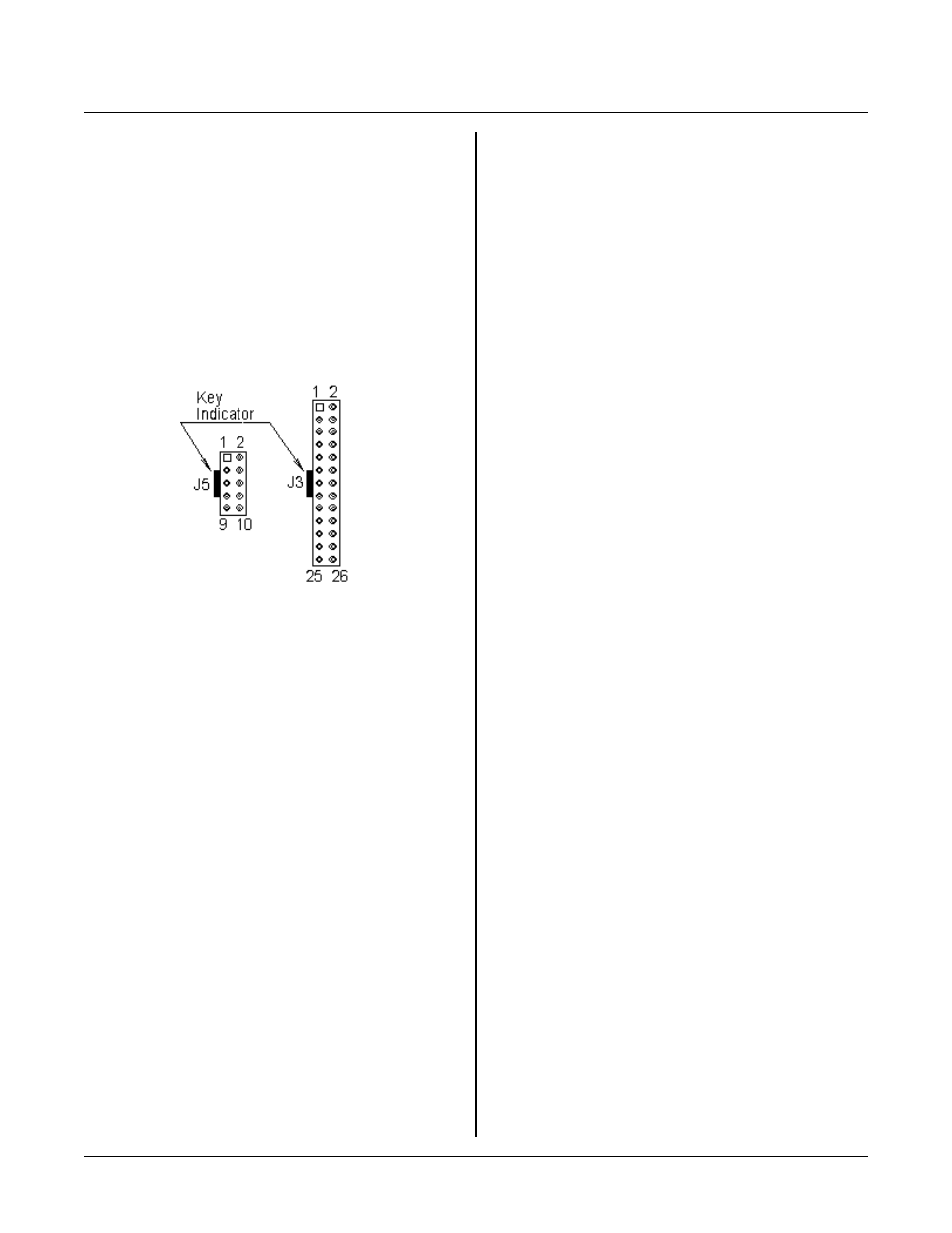
Figure 6-2 Connector
n u m be r in g sc h em e
When an input line is brought low, that line
will stay low until or unless pulled high
through a 4.7K ohm, or 1 mA source
current, to + 5V. T his kind of input is not
a problem when driven by external TTL
outputs. However, if driven by open
collector circuits or switches, then a 4.7K
or lowe r pull up r esistor is nec essary to
override the latch. This latch is only active
on 82C55 port A.
CONNECTOR NUMBERING SCHEME
C o n ne c to r s J 3 , J5 , a n d J 7 ar e n um b e r ed in a sc h em e
similar to above. The view is looking down at the top,
or com ponent side of th e board . T he squar e pad, visible
on the circuit side of the board, designates pin 1. The
white line next to the connector outline designates a key
plug, if used, on the ribbon connector.
J3 DIGITAL PORT
Lines are accessed using the LINE or LINEB
comm ands. Lines ar e configur ed for inp uts or outpu ts
using the CONF IG LINE command.
WARNING:
When configuring lines for outputs using CONF IG
LINE, lines go low momentarily (less than 10
micro-seconds) until they are set high again per the
d a ta in th e co m m a nd li ne . R e fe r to C O N F IG L I N E
command in Appendix A for more inform ation.
J3 is used to interface opto modules (using MPS series
racks), drive small r elays, solenoids, motors, or lamps,
and pro vide gener al purpos e TTL I/O to other logic
devices or mechanical switches. J3, port A is also used
to drive the LC D display port at J4. J3 pin out and a list
of shared pins is at the end of this section.
The lines on J3 are divided into 3 eight bit groups from
an 82C55. Ports A and B are configured as all inputs or
outputs. Port C is progr amm ed as one gr oup of 8 inputs
or outputs or as two groups of four lines (upper and
lower C). T he four lines in upper and lower C can each
be prog ram med as a ll inputs or outp uts. R efer to T able
6-1 to determine the opto channel or J3 pin number for a
port. Use C ONF IG LIN E 100 (Se e Appen dix A) to
configure por ts A, B, and C for inputs or outputs.
Digital I/O lines at J3 are pulled to + 5 volts or ground
through 100K resistor packs. See N OTE above
regard ing Port A latching inputs.
Application program J3-1. BAS configures J3 for 12
inputs and outpu ts. P orts A a nd upper C ar e outputs
while ports B and lower C are inputs. CONFIG LINE,
LINEB, and LINE# com mands are used.
Digital I/O software commands
A brief description of how digital I/O commands are
used is described below. These commands are further
describe d in the RP BASIC -52 softwar e manua l.
CON FIG LIN E determines which lines are inputs and
outputs.
CONFIG LINE 100,3,255,0,255
Configures port A for output, B for input, upper C
and output, and lower C as input. The last three
numbers determine what state the outputs are after
initialization. You can set certain bits high and
others low by adjusting output data .
LINEB 0a202h,35
W r i te s a b y te - wi de d at a v a lu e of 3 5 t o p o r t C .
A = LINEB(0a201h)
Reads byte-w ide data a t port B.
The 82C 55 allows yo u to read b ack wha t was wr itten to
at a port. It is possible to read a port, set (or clear) a
bit, and w rite out to it again as follows:
LINEB,0a200h,LINEB(0a200h) .OR. 64
The above example reads por t A, sets bit 6 high, and
writes the data back ou t to the same p ort.
Ports A, B, and C are accessed at the addresses listed
below.