Remote Processing RPC-210 User Manual
Page 5
OVERVIEW
SECTION 1
Page 1-2
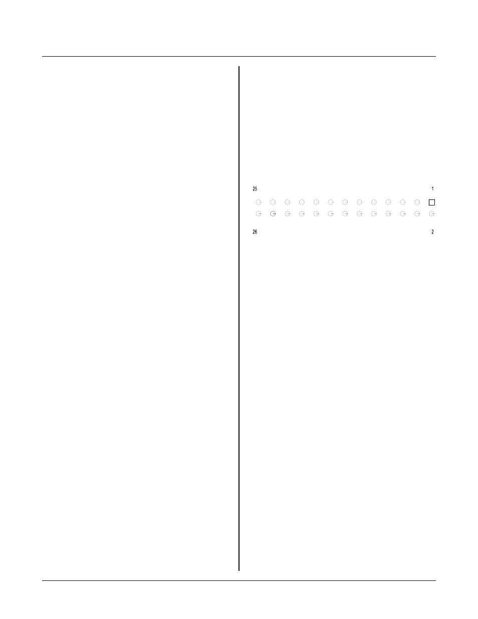
26 Pin Connector P in Out
< xxx> Paired angle brackets are used to indicate a
specific function key on your PC keyboard. For
example < esc> means the escape key.
Jx-N
Designates a pin number on a connector.
BASIC Statement types
There a re 4 gener ic types of BASIC statem ents: The first
type is a command . A command does something,
generally an output. Examples of commands are PRINT,
CLEAR, AOT, and POKE.
A function r e tu r n s a v al ue . E x am p le s ar e A IN , S I N ,
and PEEK.
The third types are control statem ents. These include
IF-THE N-ELSE, GOTO, GOSUB, and DIM. As such
t he y co n tr o l o r se t u p th e sy s te m .
The final type are multi-tasking sta tements . W hen multi-
tasking is in effect, the operating system is checking
lines for state changes, keypad port for key pad presses,
or counting pulses. For the most part, m ulti-tasking
must be set up in the program. Set up consists of a ON
multi-tasking, para meters statement and a subroutine that
is executed when conditions are met. Exam ples of
multi-tasking are ON LINE, ON COM, ON COUNT,
a n d O N K E Y P AD .
Some stateme nts are both functions and com mands,
depending upon which side of the ‘= ’ sign it is on.
Some exam ples inclu de ASC , D ATE , T IME , L INE B,
and COUNT.
Number conven tion
BASIC convention generally uses decimal for data and
address inform ation. Num bers m ay be re presente d in
hexadecimal notation. Any hexadecimal numbers are
represented by 0xxH notation. A leading 0 is necessary
when the first number begins with any letter between A
and F. Up to six digits m ay be re presente d in this
manne r. Howe ver, may com mands a nd functions on ly
accept 1, 2, or 4 hex digits.
C o n ne c to r O ri e nt a ti on a nd N u m be r in g Sc h em e
The RP C-210 uses ID C type (0. 1" center ) connectors.
There are silk screen m arks on the board to indicate the
key on the co nnector . P ins 1 and 2 ar e indicated on a ll
of the larger co nnectors.
I D C ty p e c o nn e ct or s fo ll ow a pi n o u t n u m be r in g sc h em e
shown below. View is component side. The square pad
(pin 1) is found on the circuit side.
Counting scheme is the same fo r 10, 16, and 20 pin
connectors.
Terminology
" A / D "
S h or t ha n d f or a na lo g -t o- di gi ta l c o nv e rt er . A n A / D
"measures" a voltage and converts it into a number
from 0 to 4095.
“D/A”
S h or t ha n d f or d ig it al -t o- a na lo g co n ve r te r . A D / A
accepts a digital number from 0 to 4095 and
converts it to a voltage.
" F la sh E PR O M "
Stores pr ogram s and data. Futur e flash type w ill
change to traditional type flash where 64K sectors
are erased. The BSAVE command will be changed
to add an er ase option. This is imp ortant only if
saving data to flash.
"I/O"
are input- output devices . O n the RP C-210, this
includes the RTC, expansion port, and counter.
" R T C "
is the real time clock located under the battery.
"segm ent"
is a 64K block of RAM . U p to 8 segments,