J5-keypad, Port j7 – Remote Processing RPC-210 User Manual
Page 32
DIGITAL LINES
BASIC
SECTION 6
Page 6-4
t o a m o re p ow e r fu l p r o ce s so r su c h a s th e RP C -
320.
There a re no firm guidelines for what constitutes a
“long” pr ogram. You may be able to process more than
20 line changes/Sec. if subroutines are “ short”. (In
theory, the RPC -210 can proce ss 800 line changes/
second). The problem is the time it takes to process a
RPBASIC-52 command. Allowing about 1.5 mSec/
command, it would take about 24 mSec to process 16
interrupts, even if the routines wer e simple retur ns!
Keep in mind other multi-tasking routines such as ON
COM , ON ITR, O NTICK, and ON KEYP AD that can
take up time.
If you excee d RPBA SIC-52' s ability, you are likely to
get an “INV ALID L INE N UMBE R” er ror in your
program even though the program is just fine and that
line previously executed. What is error really is is an
insidious stack error caused by the CPU stacking up
tasks and not ha ving enough time to do them all.
J5-Keypad
J5 is normally used as a keypad port. Since keypad
scanning is always active, column lines at J5 are strobed
every 100 mSec. Any data written to them will change
within 100 mSec.
If the keypad is not used, rows may be read at any time.
The statement below reads row s 1-6 at J5:
A = LINEB(0A400H) .AND. 63
Data is AN Ded to filter out unassociated r ows.
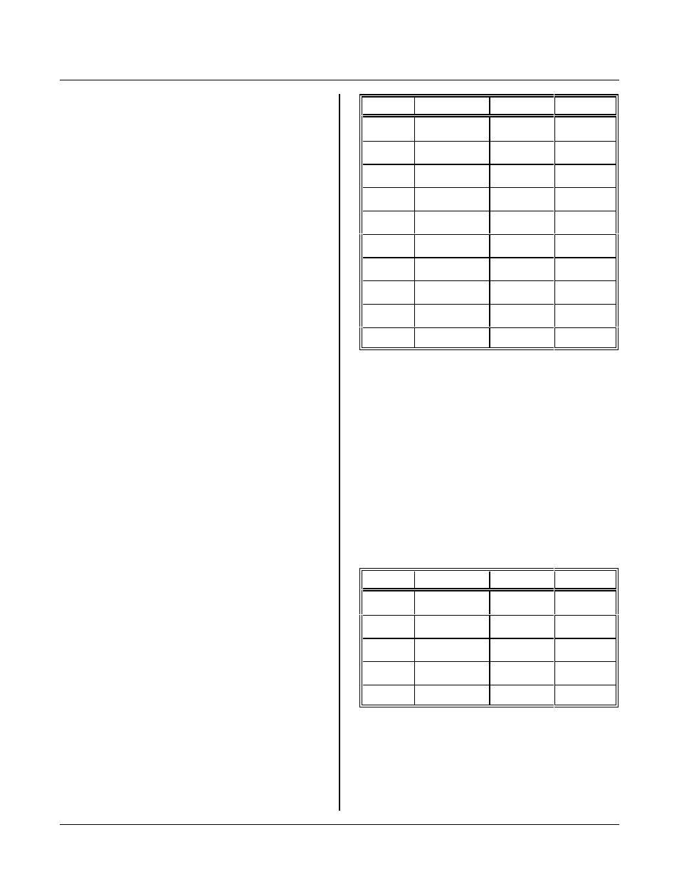
The following table shows the address and bit numbers
for row s and columns.
J5 pin
Description
Address
Bit
1
Row 1
0A400H
0
2
Col 3
0A305H
0
3
Col 2
0A304H
0
4
Row 2
0A400H
1
5
Row 3
0A400H
2
6
Col 1
0A303H
0
7
Col 4
0A306H
0
8
Row 4
0A400H
3
9
Row 6
0A400H
5
10
Row 5
0A400H
4
Rows 5 and 6 are not read by the keypad scan routine.
Port J7
J7 is a potpourri of lines. Interrupts, SP I signals, and
digital I/O lines are among them. This part discusses
only the digital I/O lines.
There are 4 input and 1 output lines at J7. lines are
accessed u sing the LIN EB statem ent.
The table b elow show s the pin num bers, address, and bit
numbers to access I/O lines at J7.
J7 Pin
Description
Address
Bit
2
Input
0A400H
6
6
Input
0A400H
5
10
Output
0A307H
0
17*
Input
0A400H
7
19
Input
0A4000H
4
*J7-17 is used for Autorun detection. When low, a
stored program will execute. After the autorun program
is executing, this input may be used for other input
purposes.
The output is set as follows: