C. example design, General description, Appendix c. example design – Altera HyperTransport MegaCore Function User Manual
Page 73
© November 2009
Altera Corporation
HyperTransport MegaCore Function User Guide
Preliminary
C. Example Design
General Description
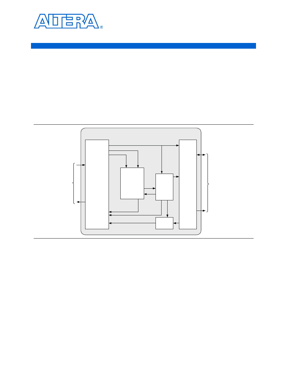
shows the high-level diagram of a example design that shows simple
usage of all of the HyperTransport MegaCore function interfaces. This design is an
SDRAM memory controller with a DMA engine that transfers data between the
HyperTransport interface and the SDRAM. In this example, the DMA engine is
programmed by a host processor on the HyperTransport link. The DMA engine
performs the requested data movement and the host processor reads the status back
from the DMA engine register.
For a data movement that reads from the SDRAM and writes to host CPU memory
through HyperTransport, the following sequence of events occurs:
1. The host CPU programs the DMA control registers using HyperTransport posted
writes. The writes come from the Rx posted interface and update the DMA control
registers.
2. The DMA state machine issues an SDRAM read request to the SDRAM control.
When the SDRAM read data returns, the DMA state machine generates the
HyperTransport post write request command, which is then multiplexed ahead of
the data and written in the HyperTransport Tx posted buffer.
3. Step
repeats until the requested DMA transfer completes and all of the SDRAM
read data is written to the HyperTransport Tx posted buffer.
Figure C–1. Example Design
Stratix Device
Write Addr
and Data
Read Addr
Read Data
HyperTransport
MegaCore
Function
Rx Posted
Rx Non-Posted
Rx Response
Tx Non-Posted
Tx Posted
Tx Response
HT Tx CAD/CTL
HT Rx CAD/CTL
Data In
Data Out
Addr Cntl/In
Data
Addr/Cntl
Resp Cmd
Resp Data
DMA State
Machine
DMA Control
& Status
Registers
HT
Link
SDRAM
Interface
SDRAM
Control
Write
Request
Multiplexer