Maps and registers, 1 flash map, 2 bios memory map – Artesyn iVPX7225 Installation and Use (April 2015) User Manual
Page 117: 1 flash map 6.2 bios memory map, Table 6-1, Flash map, Table 6-2, Bios memory map, Chapter 6, maps and registers, Chapter 6
Chapter 6
iVPX7225 Installation and Use (6806800S11C)
98
Maps and Registers
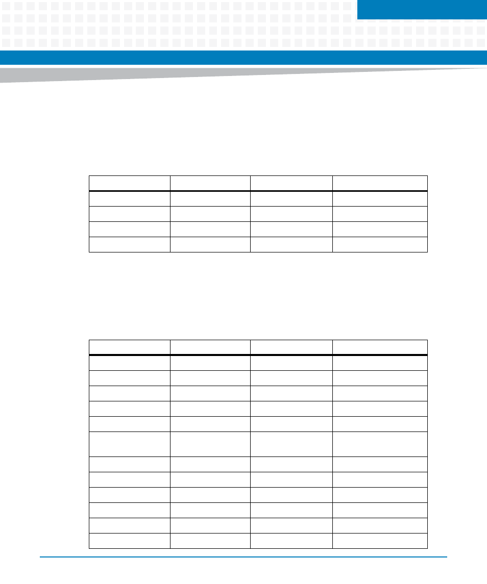
6.1
Flash Map
The following table shows the mapping of the entire 8MB flash device and shows the various
images that are stored in a specific address location.
6.2
BIOS Memory Map
The following table shows the BIOS Memory Map details.
Table 6-1 Flash Map
Start (hex)
End (hex)
Length (hex)
Area Name
0x00000000
0x00000FFF
0x00001000
Descriptor Region
0x00001000
0x00002FFF
0x00000000
GbE Region
0x00003000
0x004FFFFF
0x004FD000
ME Region
0x00500000
0x007FFFFF
0x00300000
BIOS Region
Table 6-2 BIOS Memory Map
Device
Start
End
Length
S3 Script
0x0009C000
0x0009FFFF
0x4000
Video ROM
0x000C0000
0x000CFFFF
0x10000
SMBIOS Table
0x000E0000
0x000FFFFF
0x20000
Onboard IGD GTT
0x20000000
0x201FFFFF
0x200000
Onboard IGD I/O
0x40004000
0x40004FFF
0x1000
PCI Address Space
Starting at:
0xC0000000
-
-
PCI MMIO
0xF8000000
0xFBFFFFFF
0x4000000
FRAM Page
0xFE800000
0xFE80FFFF
0x10000
I/O APIC
0xFEC00000
0xFEC00FFF
0x1000
EHCI HC
0xFED08000
0xFED08FFF
0x1000
MCH
0xFED10000
0xFED19FFF
0xA000
PCH RCBA
0xFED1C000
0xFED1FFFF
0x4000