7 modem control register (mcr), Table 7-52, Modem control register (mcr) – Artesyn iVPX7225 Installation and Use (April 2015) User Manual
Page 155: Fpga registers
FPGA Registers
iVPX7225 Installation and Use (6806800S11C)
136
7.3.1.7
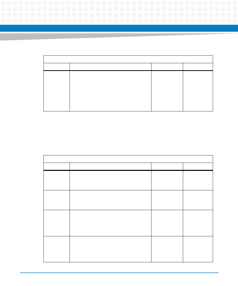
Modem Control Register (MCR)
This 8-bit register controls the interface with the modem or data set (or a peripheral device
emulating a modem).
7
Divisor latch access bit (DLAB)
Bit 7 must be set to access the divisor latches
of the baud generator during a read or write.
Bit 7 must be cleared during a read or write to
access the RBR, THR, or IER.:
1: Access to DLL and DLM registers
0: Access to RBR, THR and IER registers
0
R/W
Table 7-51 Line Control Register (LCR) (continued)
IO Address: Base +3
Bit #
Description
Default
Access
Table 7-52 Modem Control Register (MCR)
IO Address: Base +4
Bit #
Description
Default
Access
0
Data terminal ready (DTR#) output control:
1: DTR# output in low (active) state
0: DTR# output in high state
0
R/W
1
Request to send (RTS#) output control:
1: RTS# output in low (active) state
0: RTS# output in high state
0
R/W
2
User output control signal (OUT1#):
1: OUT1# output in high state
0: OUT1# output in low state
Not supported
0
R/W
3
User output control signal (OUT2#):
1: OUT2# output in high state
0: OUT2# output in low state
Not supported
0
R/W