Starting operation and diagnostics – BECKHOFF BK3000 User Manual
Page 18
Basic information
18
BK3xxx/LC3100
Starting operation and diagnostics
Installation guidelines
The "PROFIBUS Nutzerorganisation e.V." technical guidelines must be
followed when installing and laying the lead.
PROFIBUS-DP/FMS assembly guidelines
www.profibus.com
After switching on, the bus coupler immediately checks the connected
configuration. Error-free start-up is signalled by extinction of the red LED
“I/O ERR“. If the “I/O ERR” LED blinks, an error in the area of the terminals
is indicated. The error code can be determined from the frequency and
number of blinks. This permits rapid rectification of the error.
The diagnostic LEDs
The bus coupler has two groups of LEDs for the display of status. The
upper group with four LEDs indicates the status of the respective field bus.
The significance of the “field bus status“ LED is explained in the relevant
sections of this manual - it conforms to conventional field bus displays.
On the upper right hand side of the bus couplers are two more green LEDs
that indicate the supply voltage. The left hand LED indicates the 24 V
supply of the bus coupler. The right hand LED signals the supply to the
power contacts.
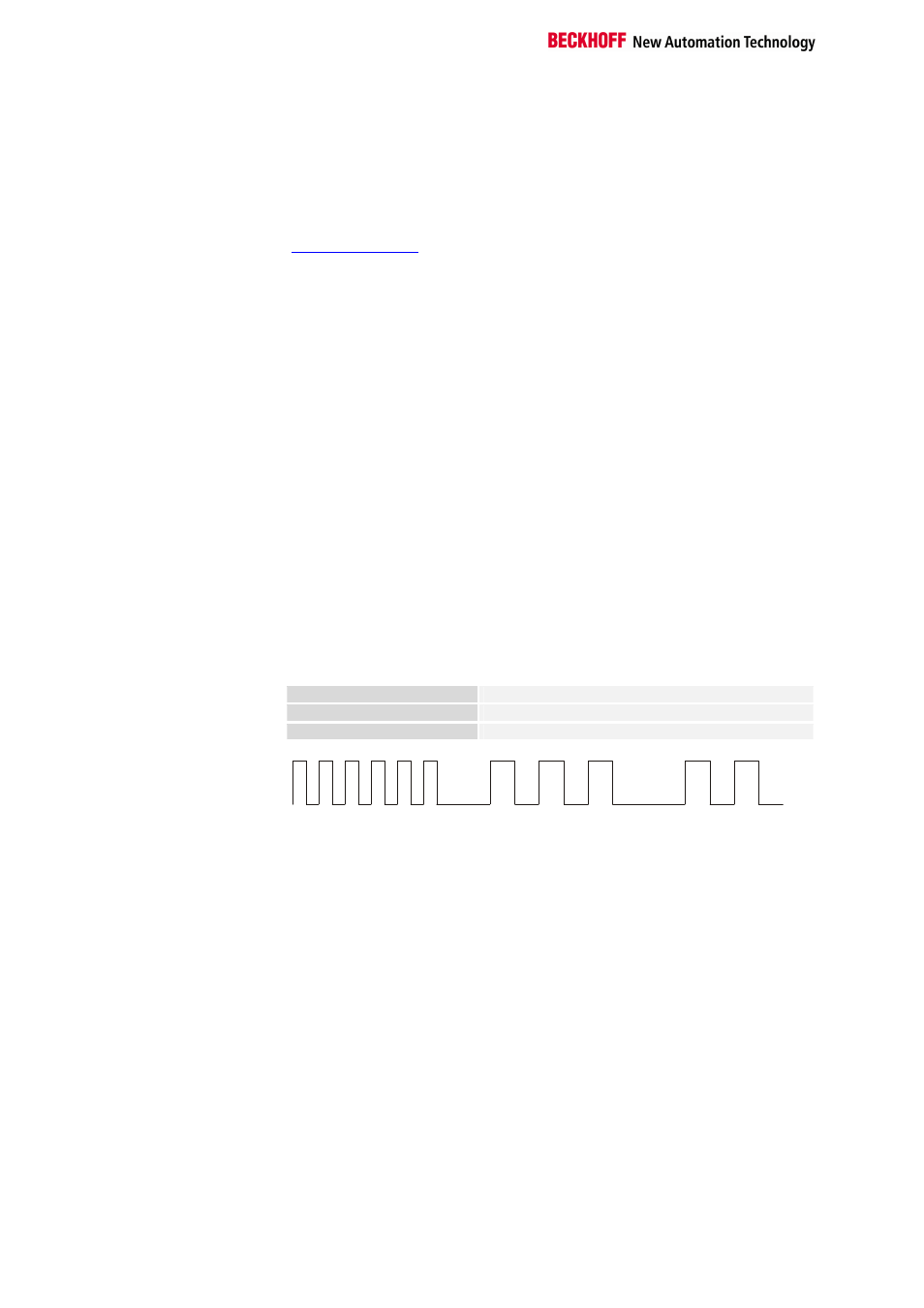
Local errors
Two LEDs, the “I/O” LEDs, in the area below the field bus status LEDs
referred to above, serve to indicate the operating status of the bus
terminals and the connections to these terminals. The green LED lights up
in order to indicate fault-free operation. The red LED blinks with two
different frequencies in order to indicate an error. The error is encoded in
the blinks as follows:
Rapid flashing
Start of the error code
First slow sequence
Type of error
Code of flashes
Second slow sequence
Location of error
Start of the error code
Error type
Error location
Start PLC