BECKHOFF BK3000 User Manual
Page 44
Appendix
44
BK3xxx/LC3100
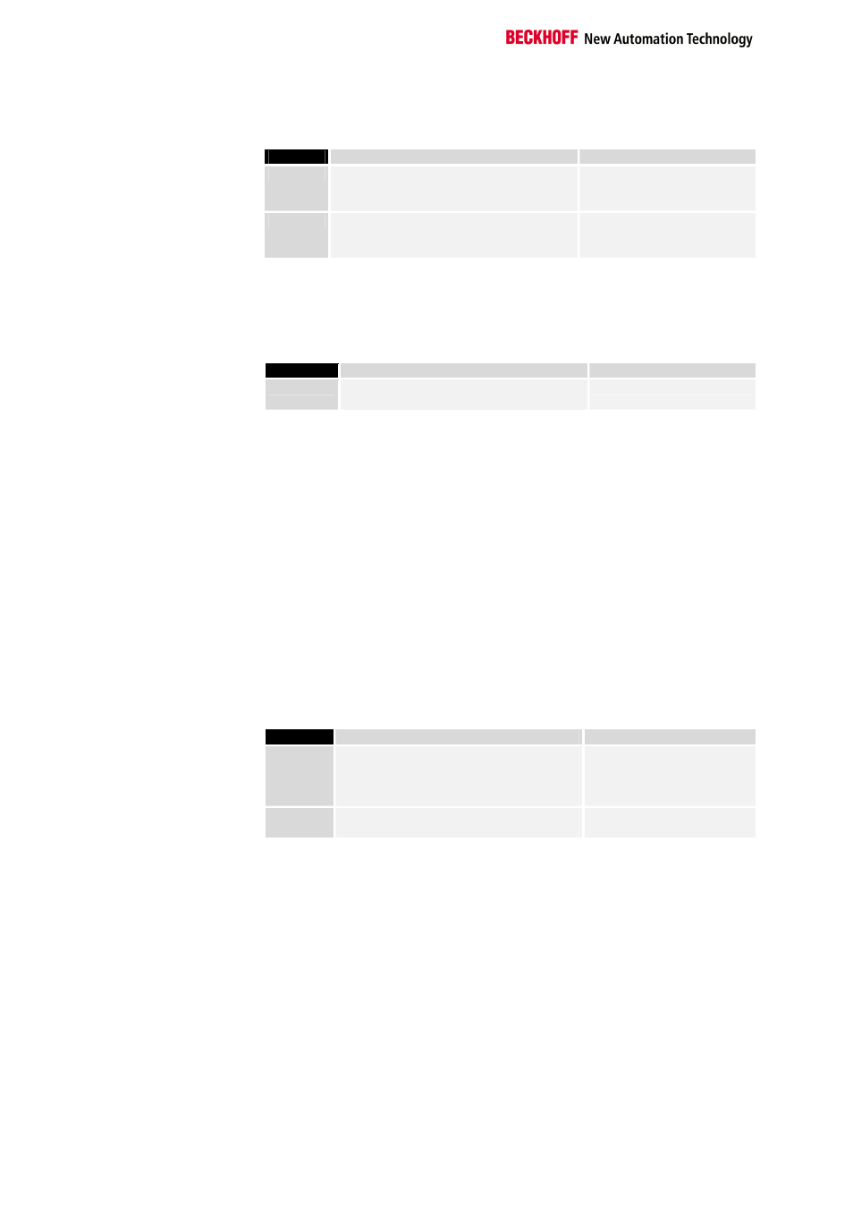
The settings for the 2 byte PLC and 2 byte diagnostic interface are located
in byte 5 of the User_Prm_Data (the default settings are printed bold):
Bit no.
Description
is supported by
Bit 0
PLC interface
0: is not used
1: is used
All BK3xx0 / LC3100
Bit 1
Event channel
0: DP diagnostics
1: diagnostic interface
BK3x10 / BK3500 / LC3100
Max. diagnostic data length Since not all DP masters can support the maximum diagnostic data length
of 64 that is possible with a bus coupler, this can be adjusted.
The settings for the maximum diagnostic data length are located in byte 11
of the User_Parameter_Data (the default settings are printed bold):
Bit no.
Description
is supported by
Byte 11
Diagnostic data length
16, 24, 32, 40, 48, 56, 64
All BK3xx0 / LC3100
Synchronous input update
If the updating of the process image is set to be synchronous with the
cycles, the terminal bus cycles is started after receipt of the
Data_Exchange telegram. The outputs are then fully current, but since the
inputs are read with the same terminal bus cycle, they can be out of date
by the time of the next transmission to the DP master, if the PROFIBUS
cycle time is significantly greater than the terminal bus cycle. For this
reason it is possible to shift the time of the terminal bus cycle after receipt
of the Data_Exchange telegram. It is also possible, if the PROFIBUS cycle
time is more than twice as long as the terminal bus cycle time, for there to
be two terminal bus cycles. The first cycle is started immediately after
receipt of the Data_Exchange telegram, (synchronous output), and the
second cycle is started at a specified time (delay time) after the first cycle
(synchronous input).
The settings for synchronous input update are located in byte 12 of the
User_Prm_Data (the default settings are printed bold), the delay time being
in bytes 13 and 14:
Bit no.
Description
is supported by
Byte 12
Bit 0/1
Synchronous input update
0: not active
1: one terminal bus cycle
2: two terminal bus cycles
BK3x10 / BK3500 / LC3100
Bytes
13/14
Delay time for synchronous input update
(in 8 microsecond units)
BK3x10 / BK3500 / LC3100
Start-up mode
In order to be able to parameterise the complex terminals at start-up using
the 2 byte PLC interface or with the DPV1 services, the bus coupler can be
switched into parameter mode at start-up, which means that after the DP
start-up is successfully completed, terminal bus cycles can still not be
carried out. After parameterisation of the complex terminals the coupler
must also be transferred into process data mode by means of the 2 byte
PLC interface, or by making use of the DPV1 services. After this the bus
coupler executes terminal bus cycles again. This makes it possible to
program the DP master in such a way that, during a DP (re-)start, the
appropriate registers for the complex terminals are transmitted via the 2
byte PLC interface or the DPV1 services before it switches the bus coupler
into process data mode. A terminal can thus be changed at any time,
without having to consider the correct register settings.
In parameter mode a distinction is made as to whether the bus coupler
must signal to the DP master that it is ready for data exchange (necessary
if the parameterisation is to take place by means of the 2 byte PLC
interface) or whether it should send static diagnostics to the DP master.