BECKHOFF BK3000 User Manual
Page 31
PROFIBUS coupler BK3xx0 in the PROFIBUS DP
BK3xxx/LC3100
31
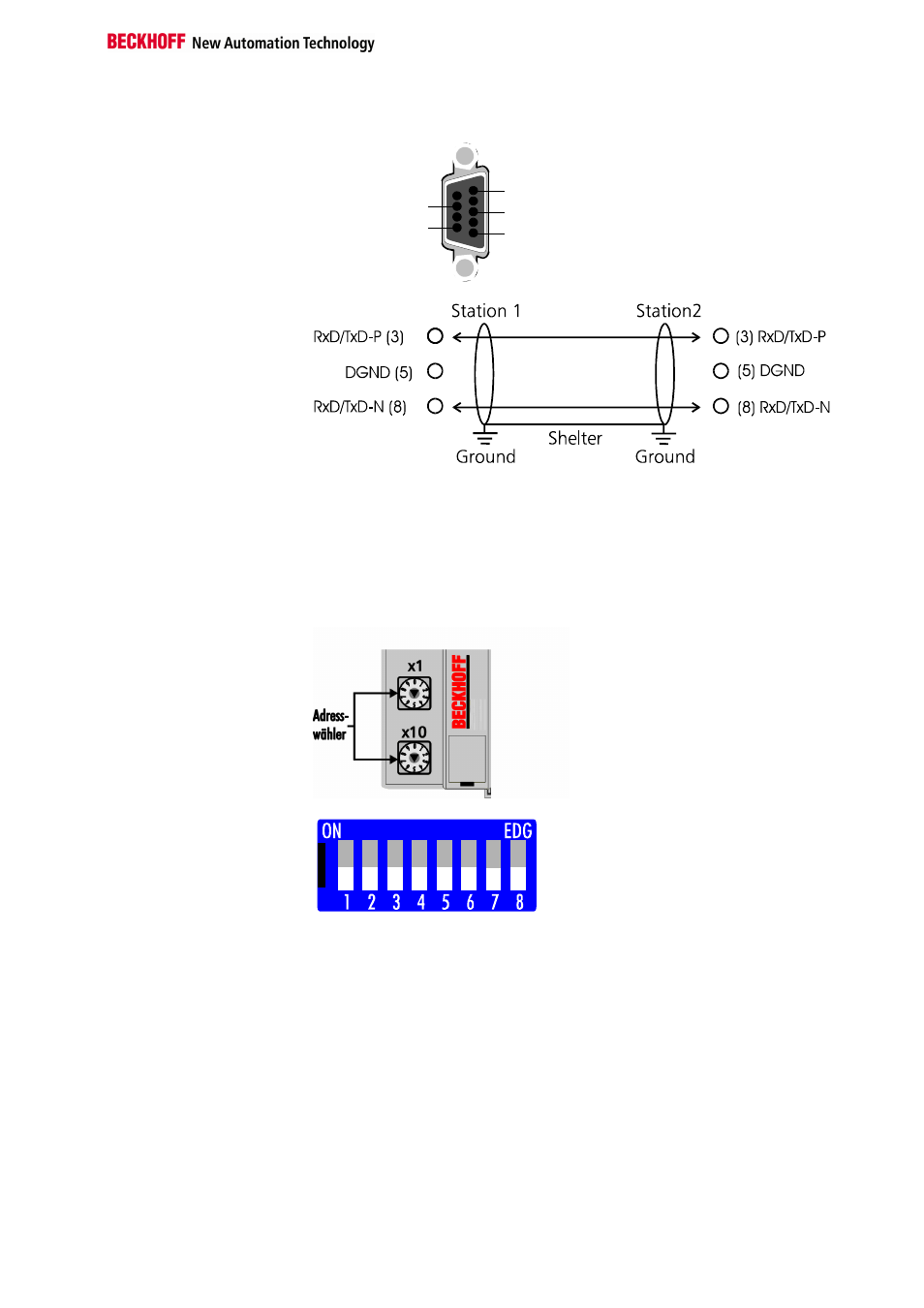
Pin assignments of the
D-Sub socket
1
6
5: GND
3: RxD/TxD- P
8: RxD/TxD- N
Cables for
PROFIBUS DP and
PROFIBUS FMS
Setting the station
Addresses
The station address is set by way of the rotary switches on the left of the
bus coupler. The address is set as a decimal number. The top rotary switch
stands for the units position and the bottom one stands for the tens position
of the address. (Example: station address 18: bottom rotary switch = 1, top
rotary switch = 8). To ensure that the rotary switch setting is saved by the
BK3xxxit must be reset (by briefing interrupting the power supply or by
means of a software reset).
Address selector
Address selector LC3100
The address of the coupler can be set by means of DIP switches 1 – 6.
Switch 1 here is the least significant bit, 2
0
, and switch 6 is the most
significant bit, 2
6
. When the switch is ON the bit is set. The address can be
set in the range from 0 to 127 (e.g. node ID = 14 -> switch 2, 3, 4 to ON),
but the address 0 is not allowed. DIP switch 8 has no function.
In systems which contain more than two stations, all the subscribers are
connected in parallel. The bus cable must always be terminated at the
ends of the lines, to prevent reflections and the transmission problems they
cause.
In order to loop the cable through without any gaps it is necessary to affix
two cables within one plug. Siemens’ SINEC L2 bus connections are very
suitable for this. These SINEC plugs are constructed to accommodate two
bus cables with the corresponding wire terminals and shielding. At the end
of the line you can use a small switch in the plug to activate the terminating
resistor. Please observe the manufacturer’s assembly instructions.