S5 example – BECKHOFF BK3000 User Manual
Page 33
PROFIBUS coupler BK3xx0 in the PROFIBUS DP
BK3xxx/LC3100
33
All the byte oriented bus terminals must first be entered into the
configuration in the sequence in which they are plugged in. No distinction is
made here between input terminals and output terminals. The bit-oriented
bus terminals come next. These are always rounded up to one byte, so that,
for instance, 6 digital terminals with two channels (which therefore comprise
12 bits) are represented by two bytes, the extra 4 bits being filled with
zeroes. The GSD file contains the 8/16/32... digital inputs and/or outputs for
the bit-oriented terminals.
For the byte oriented bus terminals, only the initial identification plus place-
holders is given (e.g. KL3XXX) rather than the full terminal name. All of
these terminals are equal in the size of their process images. After this, the
number of channels can be specified. This is useful if it is desired to assign
different addresses in the PLC to the terminal channels.
16In
only user data
24In/8Out
user data with control and status (only in the KL3XXX)
8In/24Out
user data with control and status (only in the KL4XXX)
24In/24Out complete process image
The Appendix contains more detailed information.
S5 Example
Example for Master IM308,
connection for Simatik S5
PLC
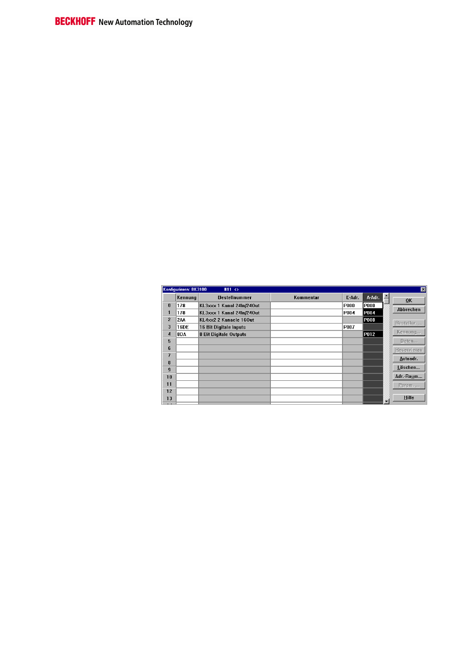
The window illustrates the configuration of an IM308-C with a BK3000
slave and with station number 3. Bus terminals:
8 x KL1002,
4 x KL2012,
1 x KL3002 and
1 x KL4002
are connected to the BK3000 bus coupler. The arrangement of the bus
terminals next to the bus coupler is not significant for the assignment of
identifications to digital inputs and outputs. It is only the width, in bits, of the
bus terminals in the K bus, and therefore in the process image, that
matters. For the byte-oriented bus terminals the sequence always starts in
the sequence as seen from the left. The listing of the byte-oriented bus
terminals is followed by that of the bit-oriented digital bus terminals. The
analogue bus terminals can be identified as two individual inputs or as
double channel.
If the composition shown above is extended with a KL3002:
8 x KL1002,
4 x KL2012,
1 x KL3002 and
1 x KL4002
1 x KL3002 (additional)
the extension must be inserted into the list at the second location. The
entries for the digital terminals are pushed correspondingly downwards.