3 parameter value pwe, 2 the process data channel (pzd), Data format, parameter – BECKHOFF AX2000 PROFIBUS DP communication profile User Manual
Page 18: Parameter value, Parameterization of the amplifier, Process data channel, Parameter value pwe, The process data channel (pzd)
3.1.3
Parameter value PWE
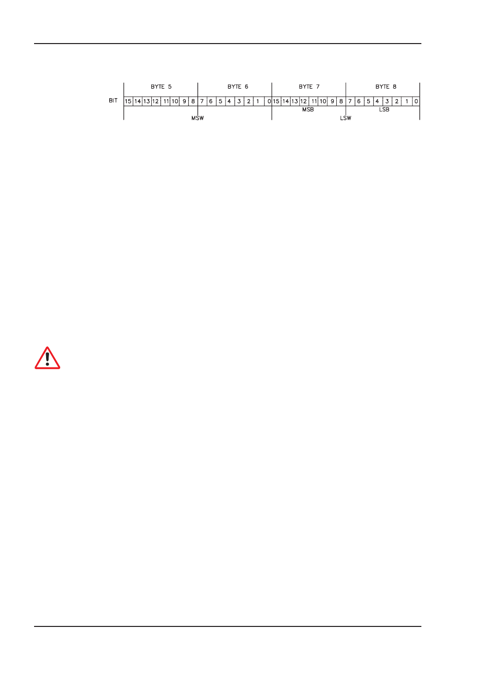
The data for the PNU-variable is contained in the PWE, and is placed flush right (PKE):
4-byte data (double-word)
PWE 5-8 (PWE 8 LSB)
Commands are transferred right justified with task ID 3. If a command cannot be executed, the
response identification AK = 7 signals the error, and an error number is given out. The error num-
bers are described on page 17.
3.2
The process data channel (PZD)
Cyclical data are exchanged across the PROFIBUS through the process data section of the 20-byte
telegram. Each PROFIBUS cycle triggers an interrupt in the AX2000/2500 and new process data is
exchanged and processed. The interpretation of the PZD by the amplifier depends on the operating
mode that is set. The operating mode is set through a PROFIBUS parameter (PNU 930,
ð p. 23).
In all operating modes, data word 1 of the process data (PZD1) in the direction from control system
to AX2000/2500 is used for instrument control, and in the direction from AX2000/2500 to control
system it has the function of a status indicator for the amplifier.
The interpretation of the process data PZD2 – PZD6 changes depending on the operating mode, as
can be seen in Chapter 5.2.
Caution:
When the AX2000/2500 is switched on, the PROFIDRIVE operating mode that is always set to
–126 (safe state). Before changing the operating mode, bit 10 of the control word STW must
always be set to 0. The new operating mode only becomes active when bit 10 of the control
word is set to 1 (see p. 23).
18
PROFIBUS for AX2000/2500
Profile of AX2000/2500
12/05
BECKHOFF