Comtech EF Data RSU-503 User Manual
Page 15
RSU-503 Redundancy Switch Unit
Introduction
Rev. 8
1–3
Although there are no external indicators or switches (due to the nature of the
weatherproof housing), there is an access panel that can be removed, allowing use of
internal switches and indicators (refer to Chapter 4 for more information).
Note: The internal indicators and switches are only used for factory testing and
troubleshooting.
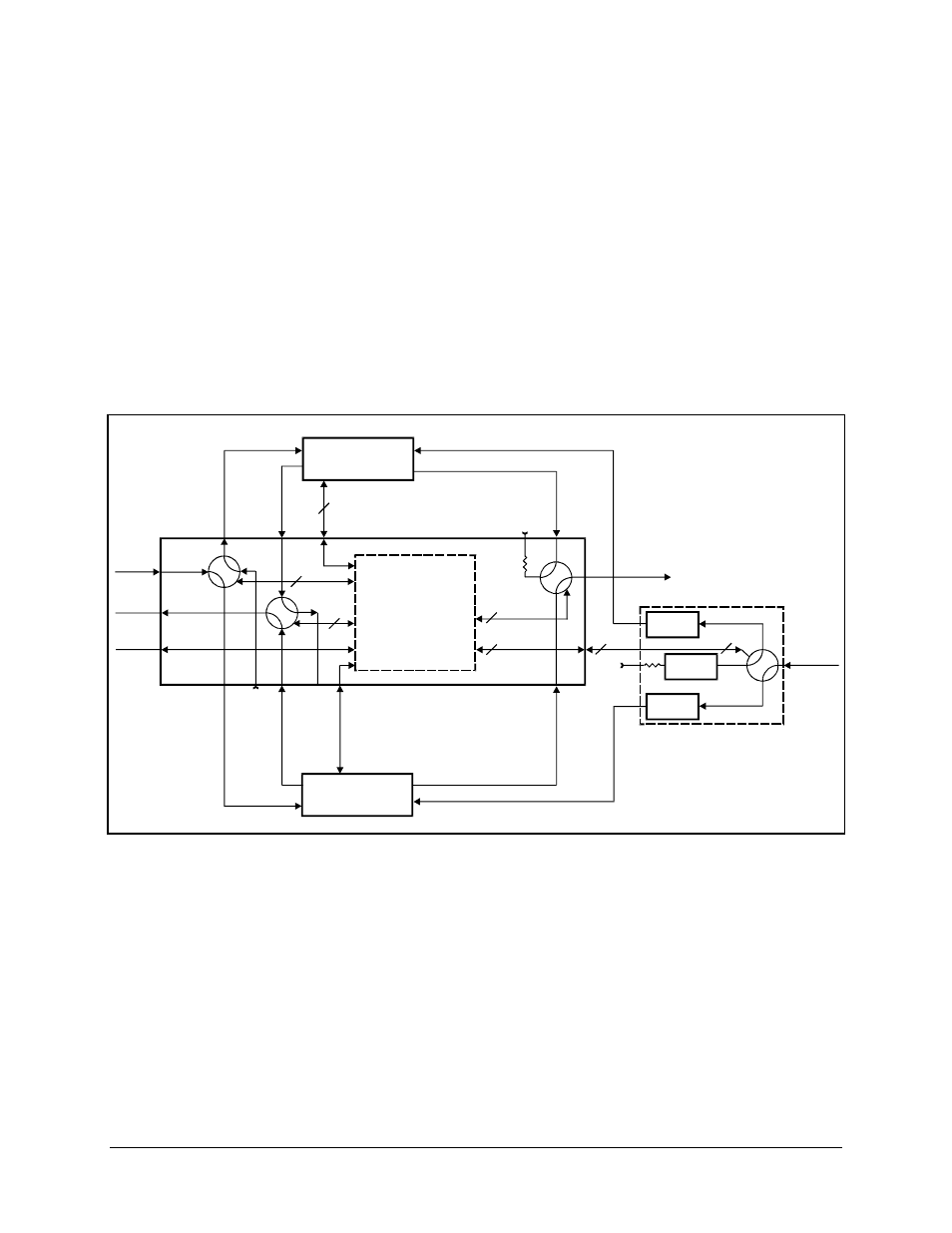
The system, during setup and while running, is intended to be controlled remotely.
Refer to Figure 1-2 for an interconnection block diagram of the switch.
RFT-xxx
# A
RFT-xxx
# B
M&C
AS/3002
M&C - RS-232
A
CA/3005
CA/3004
AS/3000
CA/1530
26
J1
J14
J5
J6
J12
J13
26
P21
P20
J8
J15
J16
S1
J2
S2
6
6
3
3
3
4
4
4
2
2
2
1
1
1
J4
TNC
TNC
TNC
TNC TNC
RSU-503
6
6
6
N
N
J9
S3
N
J11
N
J3
J10
INPUT
TO
ANTENNA
FROM
ANTENNA
REDUNDANT SWITCH PLATE
WG TO N
ADAPTER
LNA
# B
LNA
# A
LNA
TEST
LNA
WAVEGUIDE
SWITCH
CA/3004
J7
N
6
LOW LOSS REDUNDANCY SWITCH UNIT
CA/3003
M&C - RS-232
B
CA/3004
CA/1530
SHOWN WITH "B" ONLINE
CA/3005
70 MHz
70 MHz
RS-232
TNC
TNC
P19
TNC
CA/3005
IND
CA/3003
TX/IF
TX/IF
A
TX/IF
B
TX/IF
TX/RF
RF/IF
RX/RF
RF/IF
B
STANDBY
TX/IF
TEST
INPUT
STANDBY
RF/IF
TEST
OUTPUT
TX/IF
INPUT
RX/IF
OUTPUT
REMOTE
CONTROL
RX/IF
RX/IF
A
RX/RF
TX/RF
TX/RF
IND
IND
IND
Figure 1-2. RSU-503 Interconnect Block Diagram