2 waveguide and coax switch drivers, 3 lna, 4 m&c operational control – Comtech EF Data RSU-503 User Manual
Page 43: 1 communications link
Theory of Operation
RSU-503 Redundancy Switch Unit
3–2
Rev. 8
3.2 Waveguide and Coax Switch Drivers
The microcontroller creates the 500 millisecond pulses to control the positions of all four
transfer switches. Photovoltaic opto-isolated switches U8, U9, U10, and U11 transform
the +5V logic into 30V pulses to drive the latching coils of the switches.
Each microwave transfer switch contributes 0.3 dB of insertion loss, with a minimum of
70 dB of isolation.
3.3 LNA
The LNAs are powered directly from their respective RFTs through the RF coax cable.
The RFT performs a current sense on its LNA, and informs the switch by declaring a
downlink fault, if one is detected.
3.4 M&C Operational Control
3.4.1 Communications Link
The terminal functions can be remotely controlled and monitored via an RS-485 or
RS-232 communications link.
•
The RS-485 interface makes it possible to operate 255 terminals on a common
communications link.
•
The RS-232 interface is used to communicate with a single terminal.
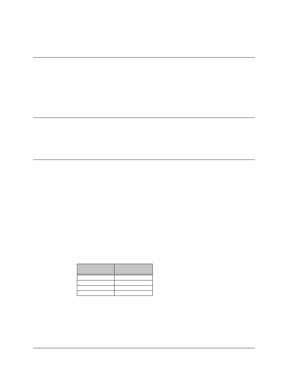
The M&C module must be hardware configured on the M&C board to one of the two
interfaces. Refer to the following table for jumper placement at JP3:
RS-485
Configuration
RS-232
Configuration
1-2
9-10
3-4
11-12
5-6
13-14
7-8
15-16