5 tx/rf output (j9), 6 waveguide switch (j10), 1 waveguide switch pinout (j10) – Comtech EF Data RSU-503 User Manual
Page 35
RSU-503 Redundancy Switch Unit
Installation
Rev. 8
19
2.4.5 TX/RF Output (J9)
The TX/RF Output connector is a 50
Ω
type N connector that carries the transmit uplink
signal from the online RFT (Unit A or B) to the antenna.
2.4.6 Waveguide Switch (J10)
The Waveguide Switch connector connects the switch to the LNA plate using a 1:1
cable.
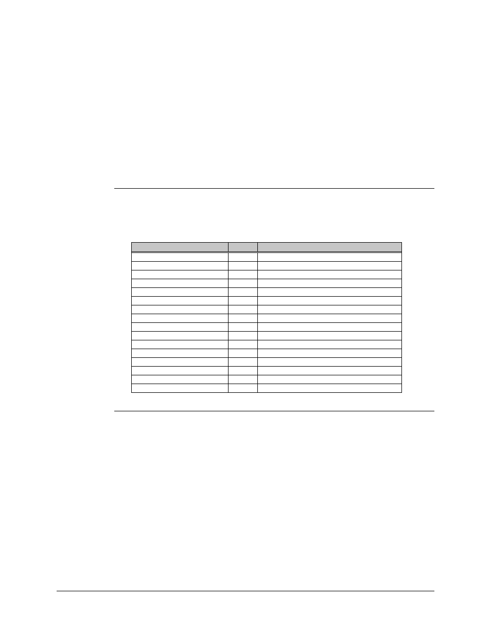
2.4.6.1 Waveguide Switch Pinout (J10)
The Waveguide Switch connector uses a 19-pin circular female connector with the
following pinouts:
Name
Pin #
Function
LNA Position 1 Command
C
+28V pulse for 500 milliseconds
LNA Command Common
G
Ground
LNA Position 2 Command
D
+28V pulse for 500 milliseconds
LNA Indicator, Position 1
H
Connects to Common when in position 1
LNA Indicator, Common
R
Ground
LNA Indicator, Position 2
T
Connects to Common when in position 2
RF Position 1 Command
E
+28V pulse for 500 milliseconds
RF Command Common
L
Ground
RF Position 2 Command
F
+28V pulse for 500 milliseconds
RF Indicator, Position 1
J
Connects to Common when in position 1
RF Indicator, Common
V
Ground
RF Indicator, Position 2
K
Connects to Common when in position 2
LNA PWR #A
A
LNA RTN #A
B
LNA PWR #B
N
LNA RTN #B
P