4 external connections – Comtech EF Data RSU-503 User Manual
Page 31
RSU-503 Redundancy Switch Unit
Installation
Rev. 8
15
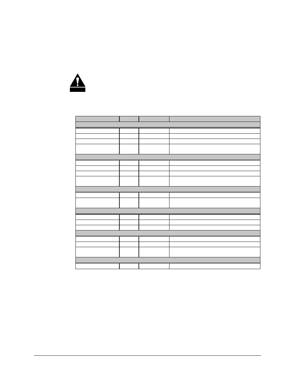
2.4 External Connections
All connections between the switch and other equipment are made through front panel
connections, as shown in Table 2-1 (refer to Figure 2-2 for connector locations).
C AU TIO N
Failure to properly connect the units will result in loss of communications
between the switch and the RFTs.
Table 2-1. External Connections
Name
Desig.
Type
Function
Switch to RFT #A (Primary)
TX/IF OUTPUT
J1
TNC, 50
Ω
IF Uplink to Unit A
RX/IF INPUT
J2
TNC, 50
Ω
IF Downlink from Unit A
TX/RF INPUT
J3
N
TX Uplink from Unit A
MONITOR &
CONTROL
J4
26-pin Circ.
Monitor and control
See Section 2.4.4 for pinouts
(See note
)
Switch to RFT #B (Backup)
TX/IF OUTPUT
J5
TNC, 50
Ω
IF Uplink to Unit B
RX/IF INPUT
J6
TNC, 50
Ω
IF Downlink from Unit B
TX/RF INPUT
J7
N
TX Uplink from Unit B
MONITOR &
CONTROL
J8
26-pin Circ.
Monitor and control
See Section 2.4.4 for pinouts
(See note
)
Switch to Antenna
TX/RF OUTPUT
J9
N
TX Uplink from online unit
WAVEGUIDE
SWITCH
J10
19-pin Circ.
Waveguide switch control
See Section 2.4.6.1 for pinouts
Standby Unit Test Ports
TX/RF OUTPUT
J11
N
TX output test signal
TX/IF INPUT
J12
TNC, 50
Ω
IF input test signal
RX/IF OUTPUT
J13
TNC, 50
Ω
IF output test signal
Switch to Modem Terminal Interface
TX/IF INPUT
J14
TNC, 50
Ω
IF Uplink
RX/IF OUTPUT
J15
TNC, 50
Ω
IF Downlink
MONITOR &
CONTROL
J16
26-pin Circ.
Modem Terminal Interface (MTI)
See Section 2.4.12 for pinouts
Ground
GND ERDE
None
#10-32 Stud
Chassis Ground
Note: Refer to Section 2.6 for addressing information.