7 tx/rf output (j11), 8 tx/if input (j12), 9 rx/if output (j13) – Comtech EF Data RSU-503 User Manual
Page 36: 10 tx/if input (j14), 11 rx/if output (j15), 2 lna plate to waveguide switch
Installation
RSU-503 Redundancy Switch Unit
20
Rev. 8
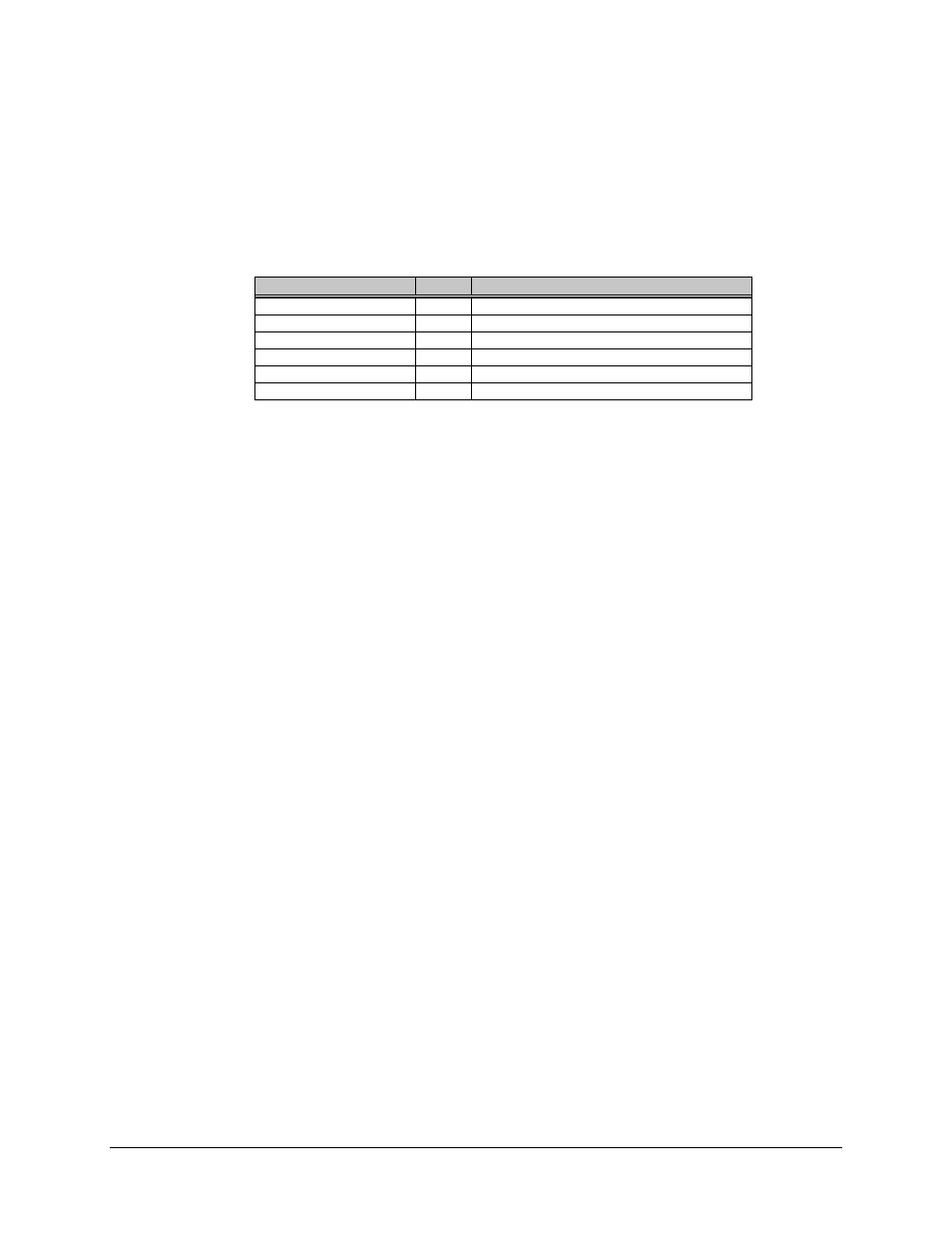
2.4.6.2 LNA Plate to Waveguide Switch
The following table outlines the pinouts of the LNA plate to Waveguide Switch cable.
This cable is internal on the redundant LNA plate.
Note: This pinout table may be helpful if an EFData Waveguide Switch is used.
Name
Pin #
Function
Command, Position 1
A
+28V pulse for 500 milliseconds
Command Common
B
Ground
Command, Position 2
C
+28V pulse for 500 milliseconds
Indicator, Position 1
D
Connects to Common when in position 1
Indicator Common
E
Ground
Indicator, Position 2
F
Connects to Common when in position 2
2.4.7 TX/RF Output (J11)
The TX/RF Output connector is a 50
Ω
type N connector used to monitor the transmit
output signal from the offline RFT. This connector is used to test the offline unit.
2.4.8 TX/IF Input (J12)
The TX/IF Input connector is a 50
Ω
TNC connector used to input the IF test signal to the
offline RFT. This connector is used to test the offline unit.
2.4.9 RX/IF Output (J13)
The RX/IF Output connector is a 50
Ω
TNC connector used to monitor the IF output
signal from the offline RFT. This connector is used to test the offline unit.
2.4.10 TX/IF Input (J14)
The TX/IF Input connector is a 50
Ω
TNC connector used to receive the IF uplink signal
from the modem. The switch routes the signal to the online RFT for transmission.
2.4.11 RX/IF Output (J15)
The RX/IF Output connector is a 50
Ω
TNC connector used to provide the IF downlink
signal to the modem (after the signal is picked up by the antenna and routed through the
online LNA and RFT).