Datatek UMI User Manual
Page 19
U N I V E R S A L M E D I A T I O N I N T E R F A C E ( U M I ) U S E R M A N U A L
04/30/09
19
4 C O N F I G U R A T I O N
4.1 OVERVIEW
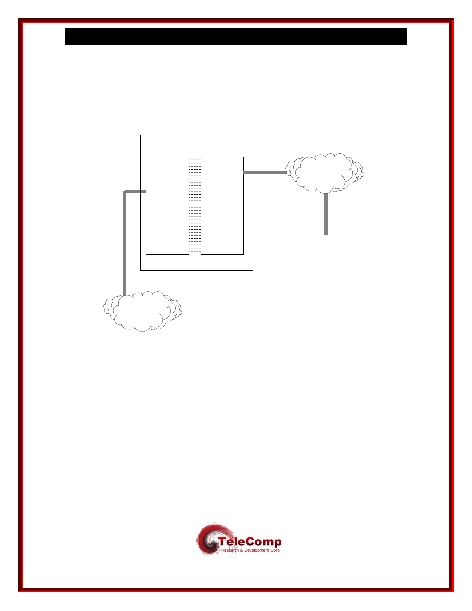
The following diagram is a functional representation of UMI operation, intended as an aid to
understanding the configuration process.
IP
Network
Any
TCP/IP
Endpoint
504 UMI
Virtual Ports
504 SAM
Sync / Async
Ports
UMI Module in BNS Node
BNS
Network
I
In order to allow it to be deployed in any BNS node without requiring an upgrade of the node
software, the UMI has been designed to appear to the node controller as a T1-Trunk-connected
SAM504. This requires the administrator to follow the same configuration command sequence
that would be used for a SAM504 (with specific entry parameters described later in this
document), using either StarKeeper
® II NMS or the node’s local console. Administration of
additional parameters specific to the UMI, referred to as “Module Based” administration, is
accomplished through the UMI’s console function, which is accessed via the RS-232 console port
on the CEY5 I/O board or via a TCP/telnet connection from a device anywhere in the IP network.
UMI “Module Based” administration can also be accomplished through StarKeeper
® II NMS.