Attaching the hopper assembly, Attaching the discharge chute – DR Power 3-Point Hitch Rapid-Feed User Manual
Page 18
14
3-POINT HITCH DR
®
RAPID-FEED™ CHIPPER
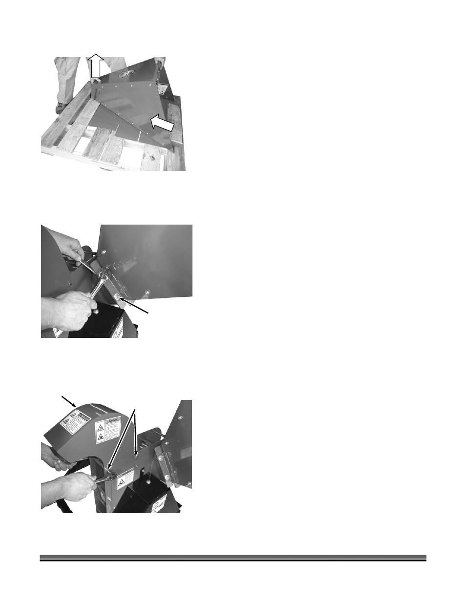
7. Pull up and then out on the small end of the Hopper
Assembly to remove it from the Pallet (Figure 8).
8. Open the Parts Box and lay out the contents of the Box
and the Hardware Package.
Compare the contents of the shipping container and the Parts
Box with the Parts Supplied list on page 12. If there are any
questions contact us at www.DRpower.com or call 1-800-DR-
OWNER (376-9637). Do not discard the shipping materials until
you are fully satisfied with your new 3-POINT HITCH CHIPPER.
Attaching the Hopper Assembly
NOTE: We recommend that you have someone help you lift the
Hopper in place and support it until it is secured to the Chipper.
Tools Needed:
• Two 1/2" Wrenches
1. Attach the Hopper Assembly to the Chipper with six
5/16"-18 x 1" Bolts, twelve Flat Washers (one Washer
on Bolt side and one on Lock Nut side) and six Nylon
Lock Nuts (Figure 9).
NOTE: Install hardware with Bolt Head on the top side.
Attaching the Discharge Chute
Tools Needed:
• Two 1/2" Wrenches
1. Position the Discharge Chute as shown and secure
with two 5/16-18 x 5-1/4" Bolts and Nylon Locknuts
(Figure 10).
Hopper
Assembly
Figure 8
Figure 10
Discharge
Chute
Bolts and
Locknuts
Hopper
Hardware
Hopper
Assembly
Figure 9