Attaching the pto shaft to the tractor and chipper – DR Power 3-Point Hitch Rapid-Feed User Manual
Page 23
CONTACT US AT www.DRpower.com or CALL TOLL FREE 1-800-DR-OWNER 19
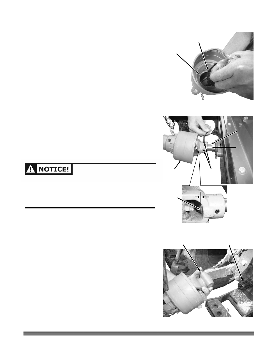
7. Insert the Shaft Halves into the Guards making sure
that the Bearing Ring Slot lines up with the Tab on the
inside of the Guards for proper installation (Figure
22).
8. Slide the two PTO Shaft Halves together.
NOTE: When inserting one half of the PTO Shaft to the other
you must line up the splines correctly (two pointed
splines and one flat spline).
See the following section to attach the PTO Shaft to the
Tractor and Chipper.
Attaching the PTO Shaft to the Tractor and Chipper
1. Insert the Key into the 3-Point Hitch Drive Shaft of the
Chipper (Figure 23).
2. Align the Key Slot of the PTO Shaft with the Key in the
Shaft and slide it onto the Shaft.
NOTE: Do not allow the 3-Point Hitch Shaft to extend more
than 1/4" into the U-Joint. This will allow proper
clearance to prevent hitting the Grease Fitting.
3. Secure the PTO Shaft with the two Set Screws from
the Hardware Package.
NOTE: If you plan to leave the Chipper attached to the
Tractor for extended periods, apply thread lock to the
Set Screws to help secure them in place.
4. Push in the PTO Shaft Spring Pin and slide the PTO
Shaft onto the Tractor Spline (Figure 24).
5. Release the Spring Pin and continue sliding the PTO
Shaft on until the Spring Pin Pops out and locks into
the detent in the Tractor PTO Spline.
YOU MUST INSTALL THE 1/4" X 1/4" X 1-1/4" KEY
SUPPLIED IN THE HARDWARE PACKAGE WHERE THE PTO
SHAFT ATTACHES TO THE CHIPPER. FAILURE TO DO SO
WILL RESULT IN DAMAGE TO THE MACHINE AND IS NOT
COVERED UNDER WARRANTY.
PTO
Shaft
Figure 23
3-Point
Hitch
Drive
Shaft
Key
Set
Screws
3-Point
Hitch
Drive
Shaft
1/4"
Max.
Spring
Pin
Figure 24
Tractor PTO
Spline
Figure 22
Bearing
Ring Slot
Guard
Tab