2 part assemblies, 3 foundation – Flowserve APKD User Manual
Page 22
APKD DOUBLE-CASE, DOUBLE-SUCTION USER INSTRUCTIONS 26999903 07-13
Page 22 of 55
flowserve.com
4.1.6.2
Installation of solid shaft driver with
jacking screws
a) Clean driver mounting flange on discharge head
and check for burrs or nicks on the register and
mounting face. Oil lightly.
b) Center motor over pump and rotate to align
mounting holes. Rotate junction box into desired
position.
c) Lower driver carefully into place. Mount the dial
indicator base on the O.D. of the motor half
coupling. Set the indicator on the pump shaft,
position the dial to zero being careful that the
indicator is in direct line with one of the
jackscrews. Record this reading then rotate the
motor shaft and indicator 180 degrees. Record
this reading being careful to note plus or minus
values. Take the difference of the two readings
and using the jackscrews move the motor one-
half of the difference. Repeat this step until the
T.I.R. reading is a maximum of 0.051mm
(0.002in.). Then repeat this step for the set of
jack screws located 90 degrees to the first set.
Once all readings are within 0.051mm (0.002in.),
tighten motor bolts and check for any movement
in readings.
d) Check driver manufacturer's instructions for
special instructions including lubrication
instructions and follow all "startup" instructions.
e) Drivers should be checked for rotation at this
time. Make electrical connections and "bump"
motor (momentarily start, then stop) to check
rotation. DRIVER MUST ROTATE COUNTER-
CLOCKWISE when looking down at top end of
motor. To change the direction of rotation on a
three-phase motor, interchange any two line
leads. To change direction of rotation on a two-
phase motor, interchange the leads of either
phase.
f) See impeller adjustment instructions (section 5.3
before bolting the pump and driver half of the
coupling together.
4.2 Part
Assemblies
Motors may be supplied separately from the pumps.
It is the responsibility of the installer to ensure that
the motor is assembled to the pump and aligned as
detailed in section 4.5. Discharge head column
piping and the pump assembly are supplied either
separately or as fully assembled depending upon the
pump size and weight. If the parts are shipped
separately, it is the customer’s responsibility to install
and align the pump with driver to the satisfaction of
Flowserve’s installation instructions.
4.3 Foundation
There are many methods of installing
pump units to their foundations. The correct method
depends on the size of the pump unit, its location and
noise vibration limitations. Non-compliance with the
provision of correct foundation and installation may
lead to failure of the pump and, as such, would be
outside the terms of the warranty.
The foundation may consist of material that will afford
permanent, rigid support to the discharge head and will
absorb expected stresses that may be encountered in
service.
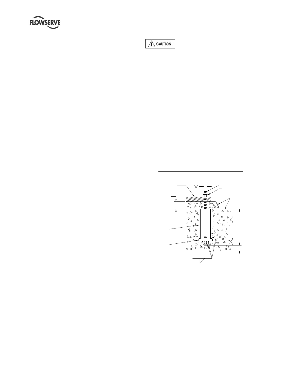
Concrete foundations should have anchor bolts
installed in sleeves that are twice the diameter of the
bolt to allow alignment and has holes in the mounting
plate as illustrated in the detail below.
When a suction barrel is supplied as in the case of the
type "TF" discharge head, the suction vessel must
provide permanent, rigid support for the pump and
motor. It should be mounted on a firm foundation.
Detail of a typical foundation bolt, grouted.
Figure 4.4
MOUNTING PLATE
25mm (1in.)
2x "D" DIA PIPE
4X "D" SQUARE
PLATE
ANCHOR BOLT
6 mm(0.25 in.)
38 mm(1.5 in.) min.
GROUT
NUT
10 X ''D"