Discharge suction – Flowserve APKD User Manual
Page 26
APKD DOUBLE-CASE, DOUBLE-SUCTION USER INSTRUCTIONS 26999903 07-13
Page 26 of 55
flowserve.com
Take into account the available NPSH that must be
higher than the required NPSH of the pump.
Never use the pump as a support for
piping.
4.6.2
Maximum forces and moments allowed on
APKD pump flanges (See table 4.6.2.1)
Maximum forces and moments allowed on the pump
flanges vary with the pump size and type. To
minimize these forces and moments that may, if
excessive, cause misalignment, hot bearings, worn
couplings, vibration and possible failure of the pump
casing. The following points should be strictly
followed.
a) Prevent excessive external pipe load.
b) Never draw piping into place by applying force to
pump flange connections.
c) Do not mount expansion joints so that their force,
due to internal pressure, acts on the pump flange.
Ensure piping and fittings are flushed
before use.
Ensure that the piping arrangement has been
provided to flush the pump before removal in cases of
hazardous liquid pumps.
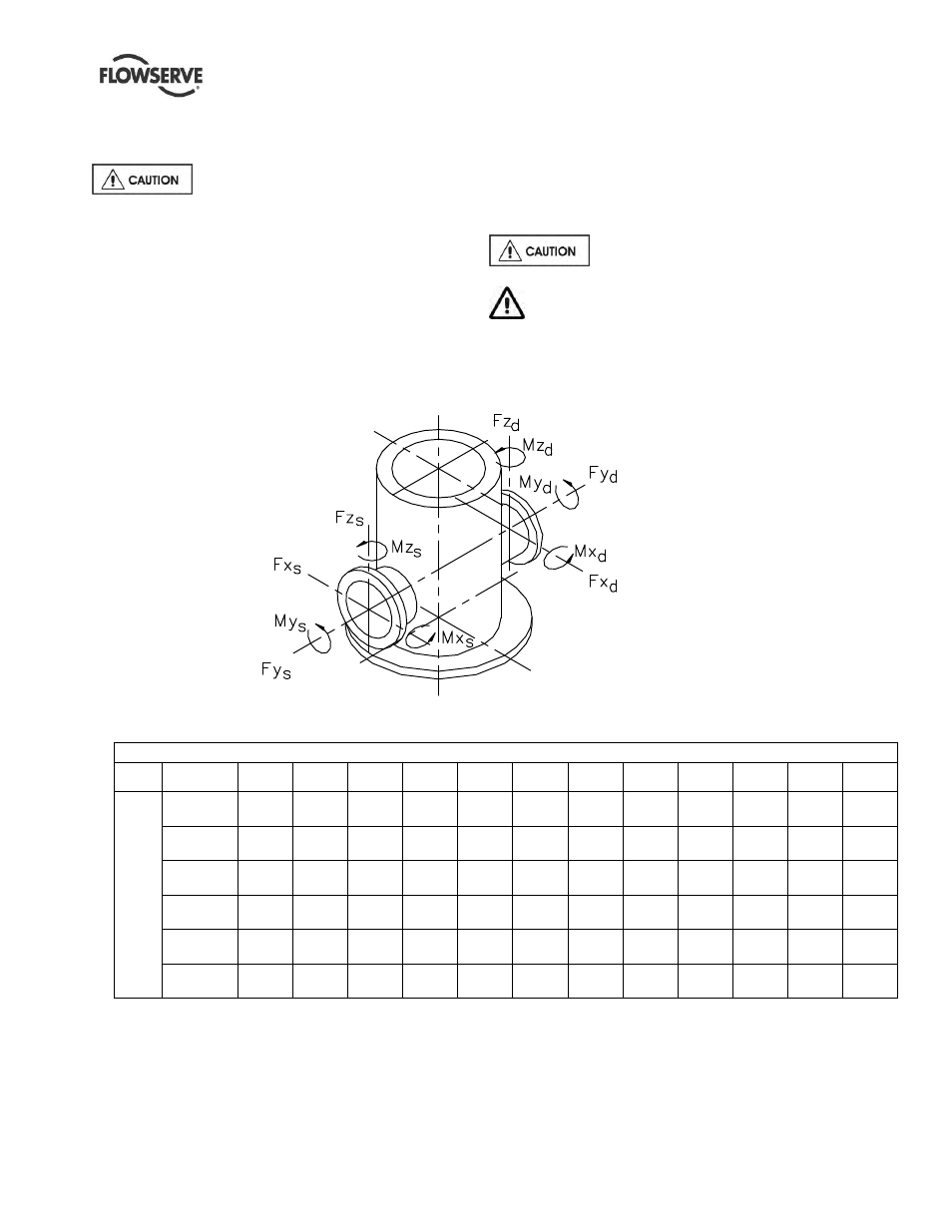
Figure 4.11
DISCHARGE
SUCTION
4.6.2.1
Table of maximum forces and moments allowed on APKD pump flanges
Discharge Head Size mm(in.)
Head
Type
Forces &
Moments
100
(4)
150
(6)
200
(8)
255
(10)
305
(12)
355
(14)
400
(16)
460
(18)
508
(20)
610
(24)
760
(30)
915
(36)
HF
LF
&
TF
Fx
1.05
(240)
1.60
(360)
2.25
(510)
2.95
(660)
3.35
(750)
3.55
(800)
4.20
(950)
4.90
(1 100)
5.34
(1 200)
6.00
(1 350)
7.10
(1 600)
8.45
(1 900)
Fy
1.35
(300)
2.00
(450)
2.95
(660)
3.65
(820)
4.00
(900)
4.45
(1 000)
5.10
(1 150)
5.80
(1 300)
6.25
(1 400)
7.10
(1 600)
8.45
(1 900)
9.80
(2 200)
Fz
0.90
(200)
1.35
(300)
1.85
(420)
2.45
(550)
2.65
(600)
2.90
(650)
3.35
(750)
4.00
(900)
4.45
(1 000)
4.90
(1 100)
5.55
(1 250)
6.25
(1 400)
Mx
1.00
(740)
1.50
(1 100)
2.10
(1 560)
2.75
(2 030)
3.05
(2 250)
3.20
(2 350)
3.65
(2 700)
4.05
(3 000)
4.45
(3 300)
5.40
(4 000)
6.50
(4 800)
7.60
(5 600)
My
0.50
(380)
0.75
(570)
1.05
(780)
1.35
(990)
1.50
(1 100)
1.55
(1 150)
1.85
(1 350)
2.00
(1 500)
2.50
(1 850)
2.70
(2 000)
3.25
(2 400)
3.80
(2 800)
Mz
0.75
(550)
1.15
(850)
1.55
(1 140)
2.10
(1 540)
2.30
(1 700)
2.35
(1 750)
2.70
(2 000)
3.05
(2 250)
3.40
(2 500)
4.05
(3 000)
4.90
(3 600)
5.70
(4 200)
Units: Force (F) in kN (lbf); Moments (M) in kNm (lbf·ft)
Forces and moments shown for TF head are for the discharge flange. For the suction flange, use the
values for the next large size head.
Loads shown are maximum allowable for standard construction. Contact Flowserve if higher values are
required or temperatures are higher than ambient