Flowserve APKD User Manual
Page 29
APKD DOUBLE-CASE, DOUBLE-SUCTION USER INSTRUCTIONS 26999903 07-13
Page 29 of 55
flowserve.com
pump rotor is in the full down position and set
the dial indicator at "ZERO".
b) Determine that the adjusting nut [66A] is in its
full down position. With the pump rotor in the
full down position, raise the shaft (by jacking) to
the upper limit of its travel. Measure the total
vertical rotor travel by use of the dial indicator.
Divide the total vertical measurement in half
and record this number.
c) With the pump rotor in the full down position
again, reset the dial Indicator at "ZERO". Turn
the adjusting nut [66A] until its upper face
contacts the face of the coupling spacer [314].
d) Place a scale against the side face of the
adjusting nut [66A] to measure the distance
that the adjusting nut moves downward as it is
backed-off from the coupling spacer [314]. Turn
the adjusting nut [66A] until the distance it has
moved away from the coupling spacer [314]
equals one half of the total vertical rotor travel,
computed and recorded in Step 2 above.
If the coupling bolt holes do not line up
when the adjusting nut [66A] has been backed-off
the desired distance from coupling spacer [314],
continue turning the adjusting nut counter-
clockwise to reach the nearest bolt hole.
5.3.2
Impeller adjustment for a solid shaft
driver
Impeller adjustment when using solid shaft drivers is
accomplished in the adjustable flanged coupling
located below the driver.
5.3.2.1
Adjusting adjustable flanged coupling
a) Assemble coupling on pump shaft and driver
shaft (if not installed earlier).
b) Check motor direction of rotation.
c) Check and write down Flowserve
recommended impeller setting for final
adjustment.
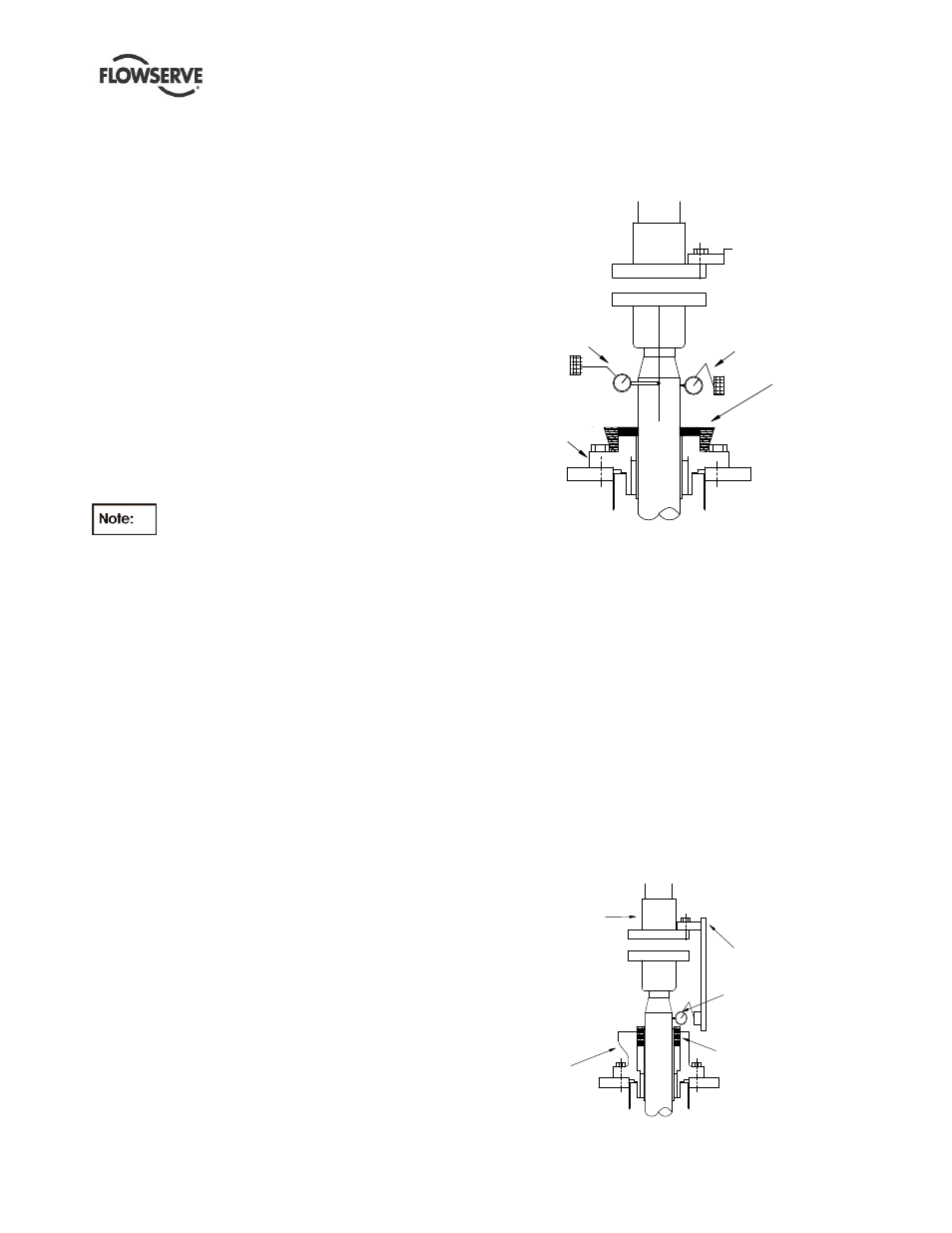
d) Pump to motor alignment and final coupling
Mount two magnetic indicator bases on the
discharge head at 90 degrees to each other
Set the indicator tips on the shaft just above
the seal and at 90 degrees to each other.
(Usually parallel and perpendicular to the
discharge nozzle) push the shaft (parallel to
discharge) back and forth (without bending
shaft)
Note and record the minimum and maximum
indicator readings. Do the same procedure
at 90 degrees to the discharge
Set the shaft in the center of the maximum
and minimum indicator readings both
directions. If the shaft will not stay in this
position, use small wooden wedges between
the shaft and seal bolts to hold the shaft.
The indicators can now be removed
Figure 5.1
IF NEEDED
INSERT
PACKING
PIECES/WEDGES
ALL AROUND
TO CENTER
THE SHAFT
DIAL
INDICATOR #1
DIAL
INDICATOR #2
MECHANICAL
SEAL
Alternate method for pump with packing:
Using an inside micrometer, measure the
space between the shaft and the packing box
bore. Do this both parallel and perpendicular
to the discharge nozzle
Using the wedges center the shaft so the
measurements taken at 180 degrees to each
other are within 0.10 mm (0.004 in.) of being
equal
(For pumps using jackscrews for motor go to
step f).
e) Mount the magnetic base on the drive half
coupling (a band clamp may be necessary to
hold base due to limited space). Position the tip
of the indicator on the pump shaft just above the
seal. Slowly rotate the driver shaft.
Figure 5.2
CENTER SHAFT IN STUFFING
BOX USING FOUR WOOD OR
METAL WEDGES
DIAL INDICATOR
RIGID BRACKET
SECURE WITH TWO BOLTS
STUFFING BOX
EXTENSION
MOTOR HALF
COUPLING