Flowserve APKD User Manual
Page 23
APKD DOUBLE-CASE, DOUBLE-SUCTION USER INSTRUCTIONS 26999903 07-13
Page 23 of 55
flowserve.com
4.3.1
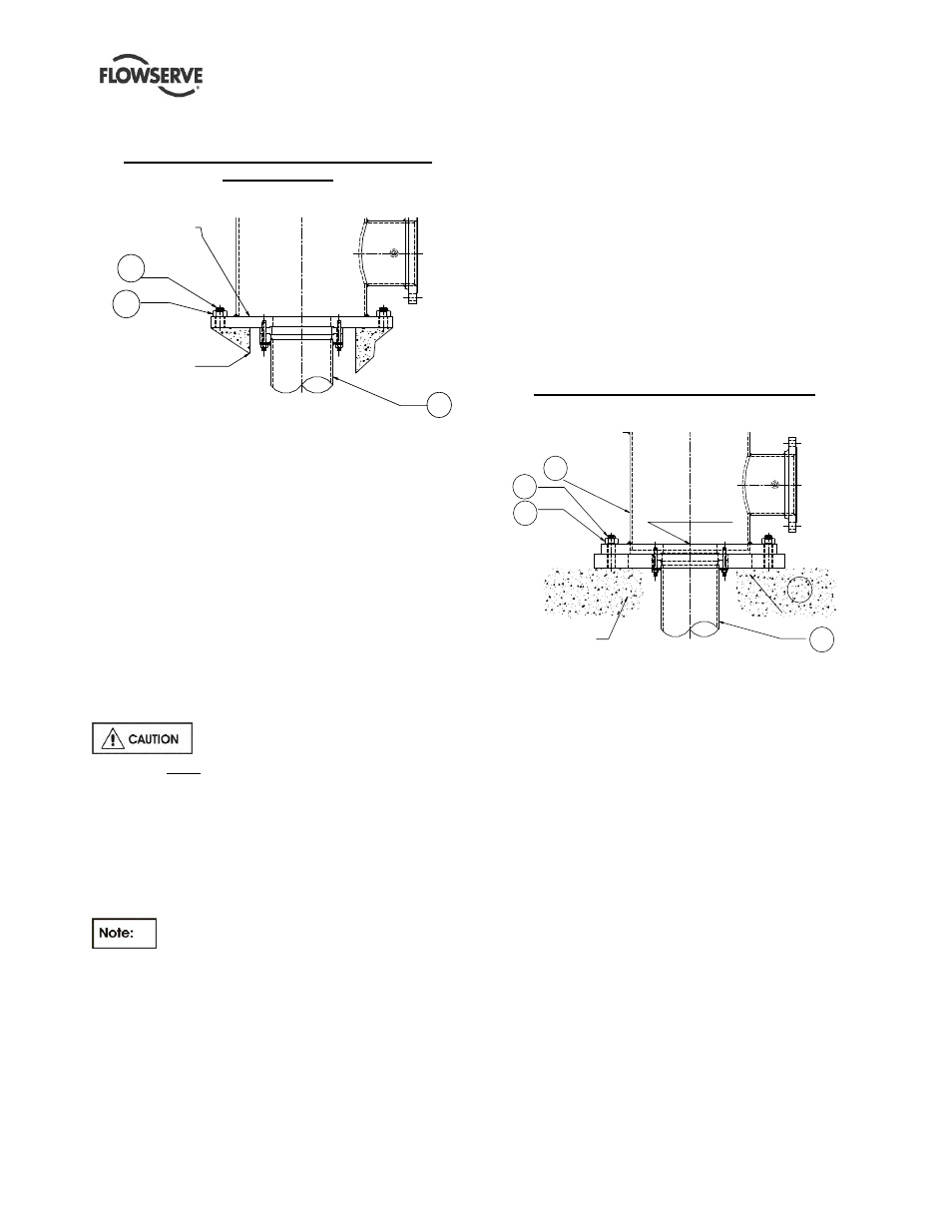
Leveling of pumps mounted on the
discharge head flange
Example of a typical discharge head with the
mounting flange
Figure 4.5
DISCHARGE
HEAD FLANGE
CONCRETE
372
373
101
Some wet pit pumps are installed directly by using
the flange that comes as an integral part of the
discharge head. The pump is lowered into the pit and
aligned with the anchor bolts [372].
The mounting flange is shimmed to achieve required
level by using a precision machinist’s level. The
pump is to be leveled to within 0.08 mm/m (0.001
in./ft). The data to be recorded for future reference.
Anchor bolt nuts [373] are tightened sufficient enough
to hold down the pump in place.
Grout is poured and allowed to set for at least 72~80
hours (cure as required) before any further work is
done on the pump.
If leveling nuts are used to level the
base, they must be backed off as far as possible prior
to grouting.
Always shim near foundation bolts and then back off
the leveling nuts. Now tighten the foundation bolts. If
done otherwise there is a risk of significantly lowering
the structural natural frequency that could result in
separation of the base from the grout.
Directly mounted pumps are not user
friendly for service. Re-installation of these pumps
requires re-leveling and re-grouting.
4.3.2
Leveling of pumps mounted on a
soleplate and the soleplate is grouted
Some pumps are mounted on a separate plate known
as soleplate [23]. In such cases, the level shall be
set with a master level or a precision machinist’s
level. The mounting surface needs to be leveled to
within 0.08 mm per m (0.001 in. per one ft).
The level should not exceed 0.125 mm (0.005 in.)
elevation difference taken on any two points on the
individual soleplate. Accurate shimming and grouting
of the soleplate is very important. Record the leveling
data for future reference. Grout the soleplate and
allow to set at least 72~80 hours (cure as required)
before the pump is lowered into the pit. Align the
discharge head boltholes with the anchor bolts [372].
Check and adjust the pump level to within 0.08
mm per m (0.001 in./ft) with respect to the soleplate
and torque the nuts [373] to the required level.
Example of pump mounted on a soleplate
Figure 4.6
372
373
CONCRETE
FOUNDATION
101
304
SOLE
PLATE
23
DISCHARGE
HEAD FLANGE
4.3.3
Leveling of pumps with the suction barrel
(also referred as “Can” VTPs)
The suction barrel [315] is first lowered into the pit and
aligned with the anchor bolts [372]. The suction barrel
flange is leveled by using a master level or a precision
machinist’s level. Levels should be taken on the
equipment mounting surfaces. The suction barrel
flange mounting surface needs to be leveled to within
0.08 mm per m (0.001 in./ft) using shims and
grouted. Allow the grout to set for at least 72~80
hours before the pump is installed. Check the barrel
mounting surface level after the grout is set and then
proceed with the pump installation. Lower the pump
assembly into the pit and align the discharge head
flange bolt holes to the anchor bolts [372].
Check and adjust the pump level with respect to the
barrel flange to within 0.08 mm per m (0.001 in./ft)
and final torque the nuts [373]. The leveling data to be
recorded for future reference.