Flowserve M-series PolyChem User Manual
Page 16
USER INSTRUCTIONS PolyChem M-SERIES ENGLISH 71569218 07-11
flowserve.com
Page 16 of 60
®
4.3.3.1
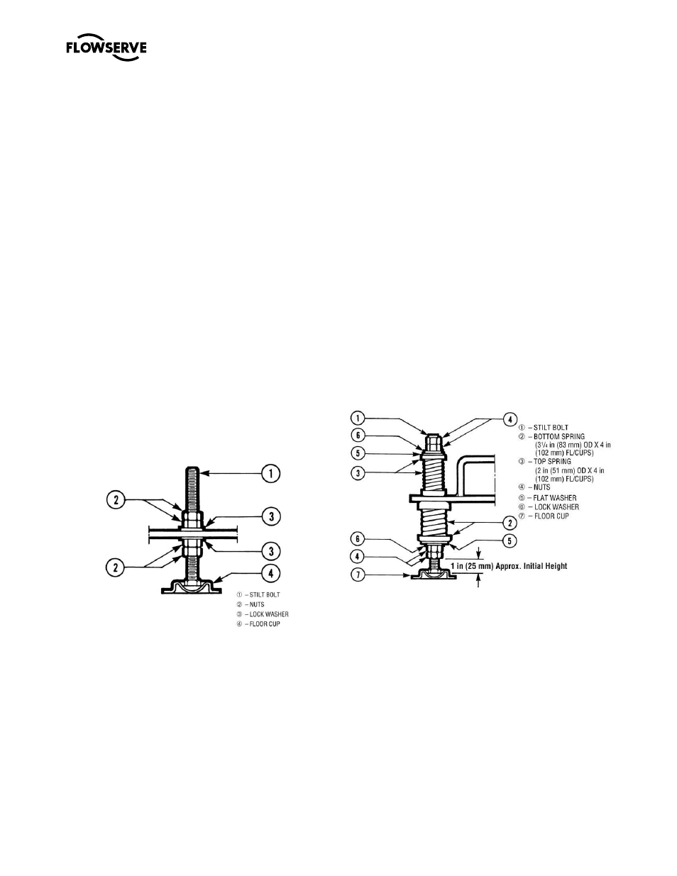
Stilt mounted baseplate assembly
instructions
Refer to Figure 4-3.
a)
Raise or block up baseplate/pump above the
floor to allow for the assembly of the stilts.
b)
Predetermine or measure the approximate
desired height for the baseplate above the floor.
c)
Set the bottom nuts [2] above the stilt bolt head
[1] to the desired height.
d)
Assemble lock washer [3] down over the stilt bolt.
e)
Assemble the stilt bolt up through hole in the
bottom plate and hold in place.
f)
Assemble the lock washer [3] and nut [2] on the
stilt bolt. Tighten the nut down on the lock
washer.
g)
After all four stilts have been assembled,
position the baseplate in place, over the floor
cups [4] under each stilt location, and lower the
baseplate to the floor.
h)
Level and make final height adjustments to the
suction and discharge pipe by first loosening the
top nuts and turning the bottom nuts to raise or
lower the baseplate.
i)
Tighten the top and bottom nuts at the lock
washer [3] first then tighten the other nuts.
j)
It should be noted that the connecting pipelines
must be individually supported, and that the stilt
mounted baseplate is not intended to support
total static pipe load.
Figure 4-3
4.3.3.2
Stilt/spring mounted baseplate assembly
instructions
Refer to Figure 4-4.
a)
Raise or block up baseplate/pump above the
floor to allow for the assembly of the stilts.
b)
Set the bottom nuts [4] above the stilt bolt head
[1]. This allows for 51 mm (2 in.) upward
movement for the final height adjustment of the
suction/discharge flange.
c)
Assemble the lock washer [6] flat washer [5] and
bottom spring/cup assembly [2] down over the
stilt bolt [1].
d)
Assemble the stilt bolt/bottom spring up through
hole in the bottom plate and hold in place.
e)
Assemble top spring/cup assembly [3] down
over stilt bolt.
f)
Assemble flat washer [5], lock washer [6] and
nuts [4] on the stilt bolt.
g)
Tighten down top nuts, compressing the top
spring approximately 13 mm (0.5 in.). Additional
compression may be required to stabilize the
baseplate.
h)
After all four stilts have been assembled,
position the baseplate in place, over the floor
cups [7] under each stilt location, and lower the
baseplate down to the floor.
i)
Level and make final height adjustments to the
suction and discharge pipe by first loosening the
top nuts, and turning the bottom nuts to raise or
lower the baseplate.
j)
Recompress the top spring to the compression
established in step g, and lock the nuts in place.
k)
It should be noted that the connecting pipelines
must be individually supported, and that the
spring mounted baseplate is not intended to
support total static pipe loads.
Figure 4-4
4.3.3.3
Stilt/spring mounted baseplates - motor
alignment
The procedure for motor alignment on stilt or spring
mounted baseplates is similar to grouted baseplates.
The difference is primarily in the way the baseplate is
leveled.
a)
Level the baseplate by using the stilt adjusters.
(Shims are not needed as with grouted
baseplates.)
b)
After the base is level, it is locked in place by
locking the stilt adjusters.
c)
Next the initial pump alignment must be
checked. The vertical height adjustment
provided by the stilts allows the possibility of