3 direction of rotation, 4 guarding – Flowserve M-series PolyChem User Manual
Page 28
USER INSTRUCTIONS PolyChem M-SERIES ENGLISH 71569218 07-11
flowserve.com
Page 28 of 60
®
5.3 Direction of rotation
5.3.1
Rotation check
5.3.1.1
Rotation check, Long-coupled pumps
It is absolutely essential that the
rotation of the motor be checked before connecting
the shaft coupling. All PolyChem M-series pumps
turn clockwise as viewed from the motor end. A
direction arrow is cast on the front of the casing as
shown in Figure 5-7. Make sure the motor rotates in
the same direction.
Figure 5-7
5.3.1.2
Rotation check, Close-coupled pumps
It is absolutely essential that the
rotation of the motor be checked. This check will
require operating the pump briefly, so the pump must
be filled with liquid. Never run a centrifugal pump dry.
To check rotation, perform the following steps:
a) Open the suction and discharge valves to allow
the pump to fill with liquid.
b) While watching the motor fan, bump the motor.
The proper direction of rotation for the pump is
clockwise as viewed from the motor end. A
direction arrow is cast on the front of the casing
as shown in Figure 5-7.
NEVER DO MAINTENANCE WORK
WHEN THE UNIT IS CONNECTED TO POWER
(Lock out.)
c) If the motor rotates in the wrong direction, reverse
any two of the three leads to the motor (3 phase
current). Bump the motor again to ensure the
proper direction of rotation.
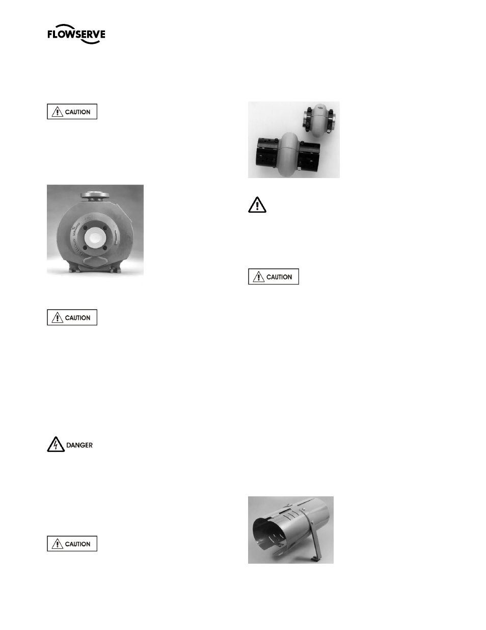
5.3.2
Coupling installation
The coupling (Figure 5-8) should be
installed as advised by the coupling manufacturer.
Pumps are shipped without the spacer installed. If
the spacer has been installed to facilitate alignment,
then it must be removed prior to checking rotation.
Remove all protective material from the coupling and
shaft before installing the coupling.
Figure 5-8
5.4 Guarding
Guarding is supplied fitted to the pump set.
In member countries of the EU and EFTA, it is a legal
requirement that fasteners for guards must remain
captive in the guard to comply with the Machinery
Directive 2006/42/EC. When releasing such guards,
the fasteners must be unscrewed in an appropriate
way to ensure that the fasteners remain captive.
Power must never be applied to the
driver when the coupling guard is not installed.
Flowserve coupling guards are safety devices intended
to protect workers from inherent dangers of the rotating
pump shaft, motor shaft and coupling. It is intended to
prevent entry of hands, fingers or other body parts into a
point of hazard by reaching through, over, under or
around the guard. No standard coupling guard provides
complete protection from a disintegrating coupling.
Flowserve cannot guarantee their guards will completely
contain an exploding coupling.
5.4.1
Clam shell guard - standard
The standard coupling guard for all PolyChem M-
series pumps is t
he “clam shell” design and is shown
in Figure 5-9. It is hinged at the top and it can be
removed by loosening one of the foot bolts and sliding
the support leg out from under the cap screw (note
that the foot is slotted). The leg can then be rotated
upward and half of the guard can be disengaged
(unhinged) from the other. Only one side of the guard
needs to be removed. To reassemble simply reverse
the above procedure.
Figure 5-9