Flowserve M-series PolyChem User Manual
Page 51
USER INSTRUCTIONS PolyChem M-SERIES ENGLISH 71569218 07-11
flowserve.com
Page 51 of 60
®
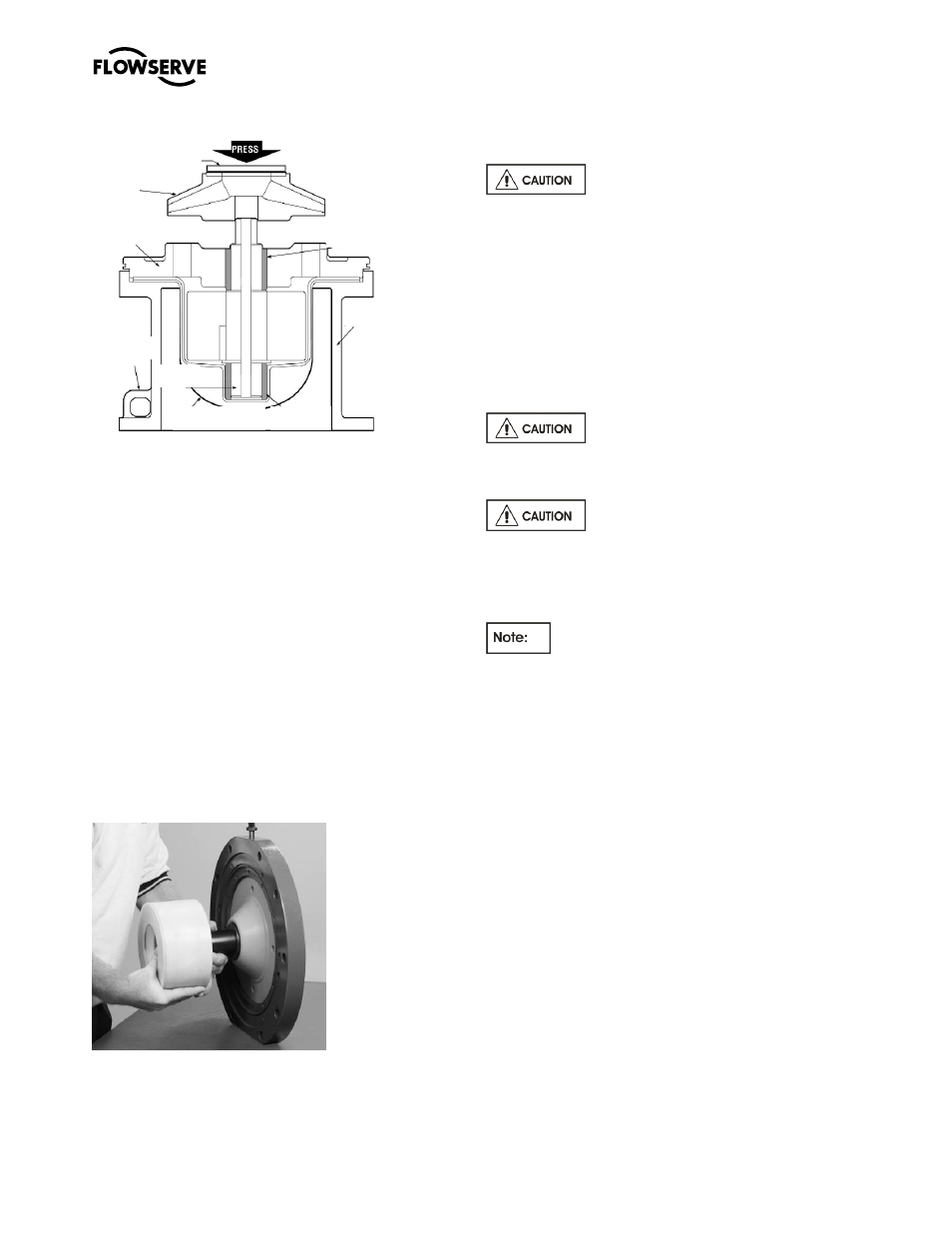
Figure 6-45
c)
Rotate the bearing holder [3830] so that holes
are
located at the 3, 6, 9, and 12 o’clock
positions with the flat being forced to be at the 12
o’clock position, which is in line with the lifting
lug.
d)
See section 6.6 for impeller assembly.
e)
Install the casing [1100] onto the lantern/bearing
holder with studs and nuts [6572 and 6580].
6.9.3.2
Group B and 2
a)
Install gasket [4610.1] into groove on bearing
holder [3830]
b)
To continue the assembly process the bearing
holder should be support horizontally. A tapped
hole is located at the 12 o’clock position on the
holder [3830] so that an eyebolt can be engaged.
An appropriate lifting device should be attached
to the eyebolt, placing it in light tension to
support the wet end. See Figure 6-45.
Figure 6-45
c)
Install the inner magnet/shaft assembly through
the bushing [3300] that is located in the bearing
holder [3830].
d)
Place the containment shell [3500] over the inner
magnet followed by retaining ring [2530].
The retainer ring [2530] is
manufactured from carbon steel and may attach to
the containment shell [3500] upon installation due to
the presence of magnets in the inner magnet
assembly.
e)
Install and tighten the twelve (12) retainer
ring/containment shell cap screws [6570.7].
f)
See section 6.6 for impeller assembly.
g)
Install the casing [1100] onto the bearing holder
with studs and nuts [6572 and 6580].
6.9.4
Mounting the wet end to the power end
Do not attempt to assemble the drive
end to the wet end without using the jackbolts. The
magnetic force can cause severe personal injury.
Be sure to engage the inner and outer
magnet assemblies evenly. Cocking of the two can
result in serious damage to the magnets and/or
containment shell. It is best to alternatively give each
bolt a turn to ensure proper and even separation.
Thread the entire length of the square head
jackbolts [6575] through the bearing housing or
lantern.
a)
Slide the wet end towards the power end until
the jackbolts [6575] engage in the recess
provided for it.
b)
Turn the jackbolts [6575] counterclockwise to
allow the wet end to slowly engage into the
power end. Alternate from one bolt to the other
to prevent the unit from cocking.
c)
Once the mating surfaces are in contact, install
fasteners [6570.6] for Group A and 1 and
[6570.8] for Group B and 2.
Bearing
holder
[3830]
Bushing
[545.1/212]
Lantern
[1340]
Containment shell
[817/224]
Shaft
[2100.1]
Lifting
Lug
O.B.
Bushing
Impeller
[2200]
Non metallic
spacer